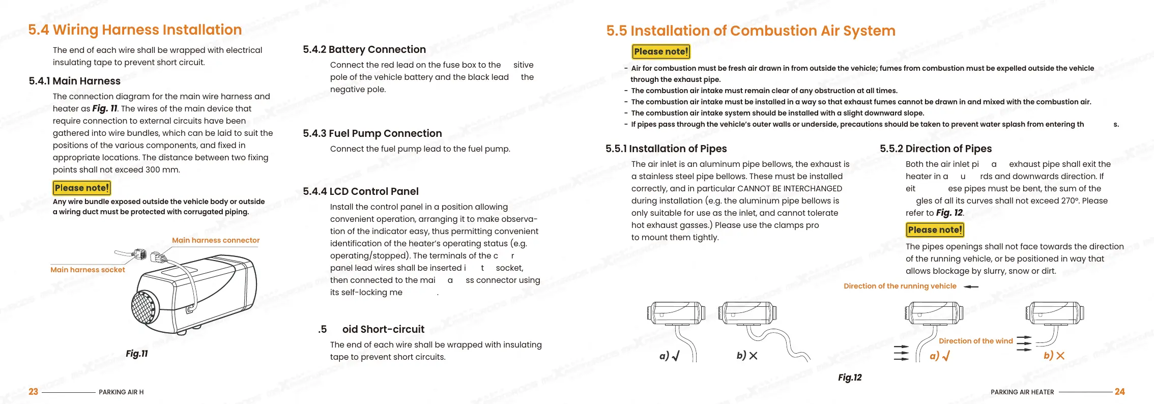
Fig.11
5.4 Wiring Harness Installation
5.4.1 Main Harness
The connection diagram for the main wire harness and
heater as Fig. 11. The wires of the main device that
require connection to external circuits have been
gathered into wire bundles, which can be laid to suit the
positions of the various components, and fixed in
appropriate locations. The distance between two fixing
points shall not exceed 300 mm.
5.4.2 Battery Connection
Connect the red lead on the fuse box to the positive
pole of the vehicle battery and the black lead to the
negative pole.
5.4.3 Fuel Pump Connection
Connect the fuel pump lead to the fuel pump.
5.4.5 Avoid Short-circuit
The end of each wire shall be wrapped with insulating
tape to prevent short circuits.
The end of each wire shall be wrapped with electrical
insulating tape to prevent short circuit.
5.4.4 LCD Control Panel
Install the control panel in a position allowing
convenient operation, arranging it to make observa-
tion of the indicator easy, thus permitting convenient
identification of the heater’s operating status (e.g.
operating/stopped). The terminals of the control
panel lead wires shall be inserted into the socket,
then connected to the main harness connector using
its self-locking mechanism.
Any wire bundle exposed outside the vehicle body or outside
a wiring duct must be protected with corrugated piping.
Main harness connector
Main harness socket
5.5 Installation of Combustion Air System
5.5.1 Installation of Pipes
The air inlet is an aluminum pipe bellows, the exhaust is
a stainless steel pipe bellows. These must be installed
correctly, and in particular CANNOT BE INTERCHANGED
during installation (e.g. the aluminum pipe bellows is
only suitable for use as the inlet, and cannot tolerate
hot exhaust gasses.) Please use the clamps provided
to mount them tightly.
5.5.2 Direction of Pipes
Both the air inlet pipe and exhaust pipe shall exit the
heater in an outwards and downwards direction. If
either of these pipes must be bent, the sum of the
angles of all its curves shall not exceed 270°. Please
refer to Fig. 12.
The pipes openings shall not face towards the direction
of the running vehicle, or be positioned in way that
allows blockage by slurry, snow or dirt.
- Air for combustion must be fresh air drawn in from outside the vehicle; fumes from combustion must be expelled outside the vehicle
through the exhaust pipe.
- The combustion air intake must remain clear of any obstruction at all times.
- The combustion air intake must be installed in a way so that exhaust fumes cannot be drawn in and mixed with the combustion air.
- The combustion air intake system should be installed with a slight downward slope.
- If pipes pass through the vehicle’s outer walls or underside, precautions should be taken to prevent water splash from entering these pipes.
a)
b)
a)
b)
Fig.12
Direction of the running vehicle
Direction of the wind
PARKING AIR HEATER
23
PARKING AIR HEATER
24
 Loading...