User Manual
EN
resistance
Measuring range Resolution Accuracy
600 Ω 1 Ω ±(2,0% + 2)
60 MΩ 1 KΩ ±(1,5% + 2)
diode or continUity test
Measurement Resolution Accuracy
Continuity
1 Ω
If the resistance is
≤ 30 Ω
we will hear a
beeping sound
Diode
1 mV
The approximate
opening voltage
can be read on the
display.
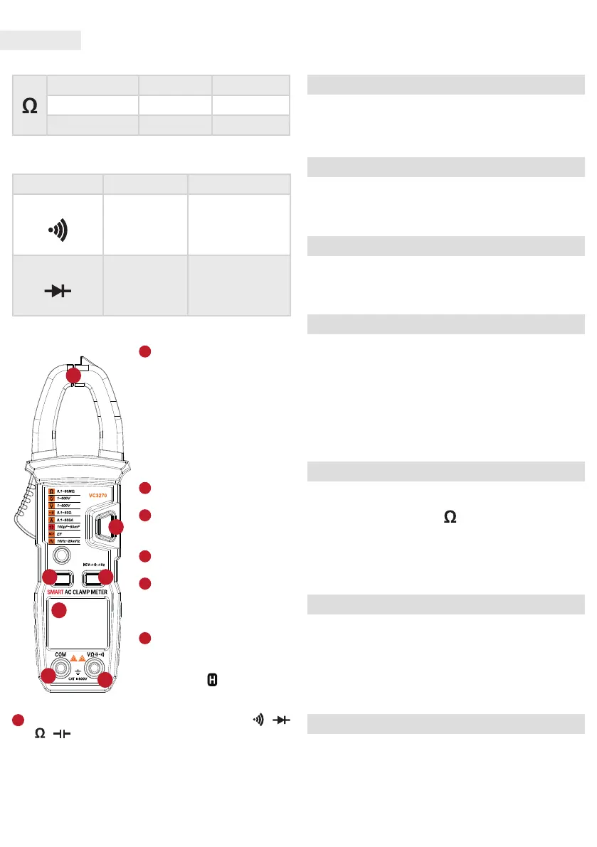
controls
1
Measuring jaws: Can be
used to measure conductors. To
achieve an accurate
measurement result, the
conductor must be located in
an enclosed area between
the jaws.
Padlock release button (trigger):
Used to open or close the
measuring jaws.
2
Display: 4 digit LCD, max.
Display: 6000
3
„COM” socket: For
connecting the black (negative)
test lead.
4
„V Ω” socket: For connecting
the red (positive) test lead.
5
Function selector (rotary)
knob: Used to select the desired
measuring function and range
and to switch the padlock on / o.
6
“H” key: After pressing the
key, the currently measured
value remains xed on the
display, while is displayed in
the upper right corner of the
display. To deactivate the mode, press the key again
7
„SET” button: mode selection button between /
and / measuring modes.
Using tHe MUltiMeter
Switching the display backlight on / o
It can be switched on after turning the rotary switch of the
device. The backlight can be turned o after the device’s
rotary switch is set to OFF, or after a few seconds the device
will turn o the backlight automatically.
DC voltage measurement
Insert the black test lead into the „COM” socket and the red
into the „INPUT” socket.
Touch the test leads to the source to be measured.
The measured value can be read on the display.
AC voltage measurement
Insert the black test lead into the „COM” socket and the red
into the „INPUT” socket.
Touch the test leads to the source to be measured.
The measured value can be read on the display.
AC current measurement
Press the trigger to release the jaws and then grasp the
conductor in the enclosed area. Make sure the jaws close
well. The measured value can be read on the display.
Note:
Let’s measure one conductor at a time!
The values of the phase running in one line and the zero
sine cancel each other out, the measured value will be 0!
Do not touch the measured conductor by hand, even if you
are sure that it is perfectly insulated.
Resistance measurement
Insert the black test lead into the „COM” socket and the red
into the „INPUT” socket.
Set the rotary selector to the
position.
Touch the test leads to the source to be measured.
The measured value can be read on the display.
Note: Before measuring resistance, make sure that the
measured source is not connected to any power source and
that all high power capacitors are discharged.
Continuity test
Insert the black test lead into the „COM” socket and the red
into the „INPUT” socket.
Use the „SELECT” button to select the appropriate
measuring mode
Touch the test leads in series with the source being tested.
If the measured resistance is less than 30 Ω, the device
will beep.
Diode measurement
Insert the black test lead into the „COM” socket and the red
into the „INPUT” socket. The polarity of the red line is positive.
Touch the red test lead to the diode anode and the black to
the cathode terminal.
Read the diode opening voltage. The value is given in mV.
 Loading...