February, 2019 eMAX-LP1502-Man Page 8 of 20
5. Input Power, Cabinet Tamper, and UPS Fault Wiring:
The eMAX-LP1502 requires 12 to 24 Vdc power. Locate power source as close to the unit as
possible. Connect power with minimum of 18 AWG wire.
Connect the GND signal to earth ground in ONE LOCATION
within the system! Multiple earth ground connections may
cause ground loop problems and is not advised.
Be sure to observe POLARITY on 12 to 24 Vdc input!
There are two dedicated inputs for cabinet tamper and UPS fault
monitoring. Normal (safe) condition is a closed contact. If these
inputs are not used, install a jumper wire.
6. Communication Wiring:
The eMAX-LP1502 controller communicates to the host via the on-board
Ethernet 10-BaseT/100Base-TX port, and/or the USB port (2.0) with an
optional USB to Ethernet adapter.
The Serial I/O device communication port (TB3) is a 2-wire RS-485
interface which can be used to connect additional I/O panels. The
interface allows multi-drop communication on a single bus of up to 4,000
feet (1,219 m). Use 1-twisted pair with drain wire and shield, 120 ohm
impedance, minimum 24 AWG, 4,000 ft. (1,219 m) maximum for
communication.
IMPORTANT NOTE! Install the termination jumper ONLY on the panel at each end of the RS-
485 bus. Failure to do so will compromise the proper operation of the communication
channel!
7. Reader Wiring:
Each Reader Port of the eMAX-LP1502 supports a reader with TTL/Wiegand (D1/D0), TTL/Magnetic
Stripe (Clock/Data), F/2F (standard or supervised) or 2-wire RS-485 OSDP signaling. Power to the
readers is selectable: 12 Vdc (VIN must be greater than 20 Vdc), or power is passed-through (PASS)
from the input voltage of the LP1502 (TB1-VIN), 300 mA maximum per reader port. Readers that
require different voltage or have high current requirements must be powered separately. Refer to the
reader manufacture specifications for cabling requirements. In the 2-wire LED mode the buzzer
output is used to drive the second LED. Reader port configuration is set via the host software.
To fully utilize each reader port:
➢ TTL signaling requires a 6-conductor cable (18 AWG)
➢ F/2F signaling requires a 4-conductor cable
➢ RS-485 signaling requires two 2-conductor cables. Use one cable for power (18 AWG) and
one cable for communication (24 AWG Twisted Pair, with drain wire and shield).
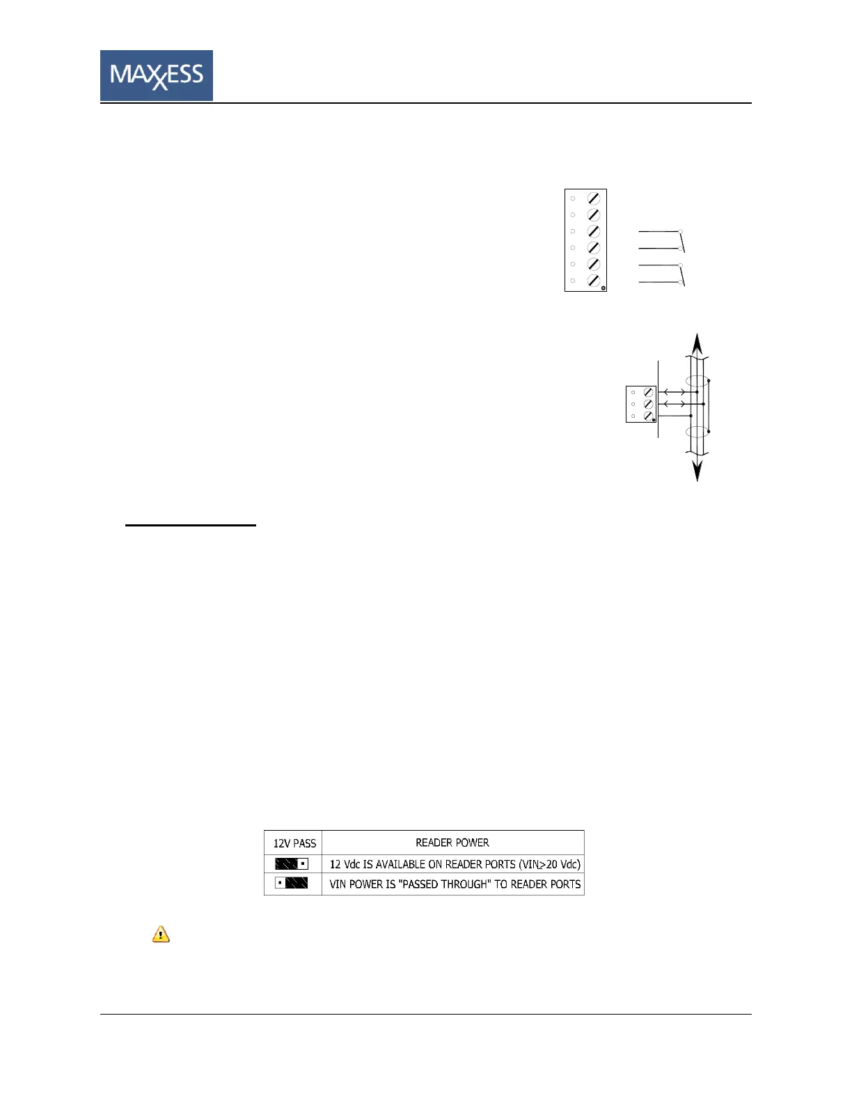
J7 – Reader Power Select
If the input voltage to the eMAX-LP1502 is 12 Vdc, jumper J7 MUST be in the PASS position.
 Loading...