ASSEMBLING AND SETTING UP
Always wear ANSI approved
safety goggles.
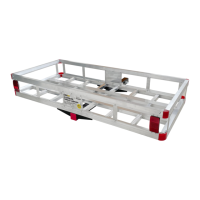
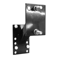
Refer to picture below of a completely assem-
bled Product, and Parts Diagram at the end of
this manual.
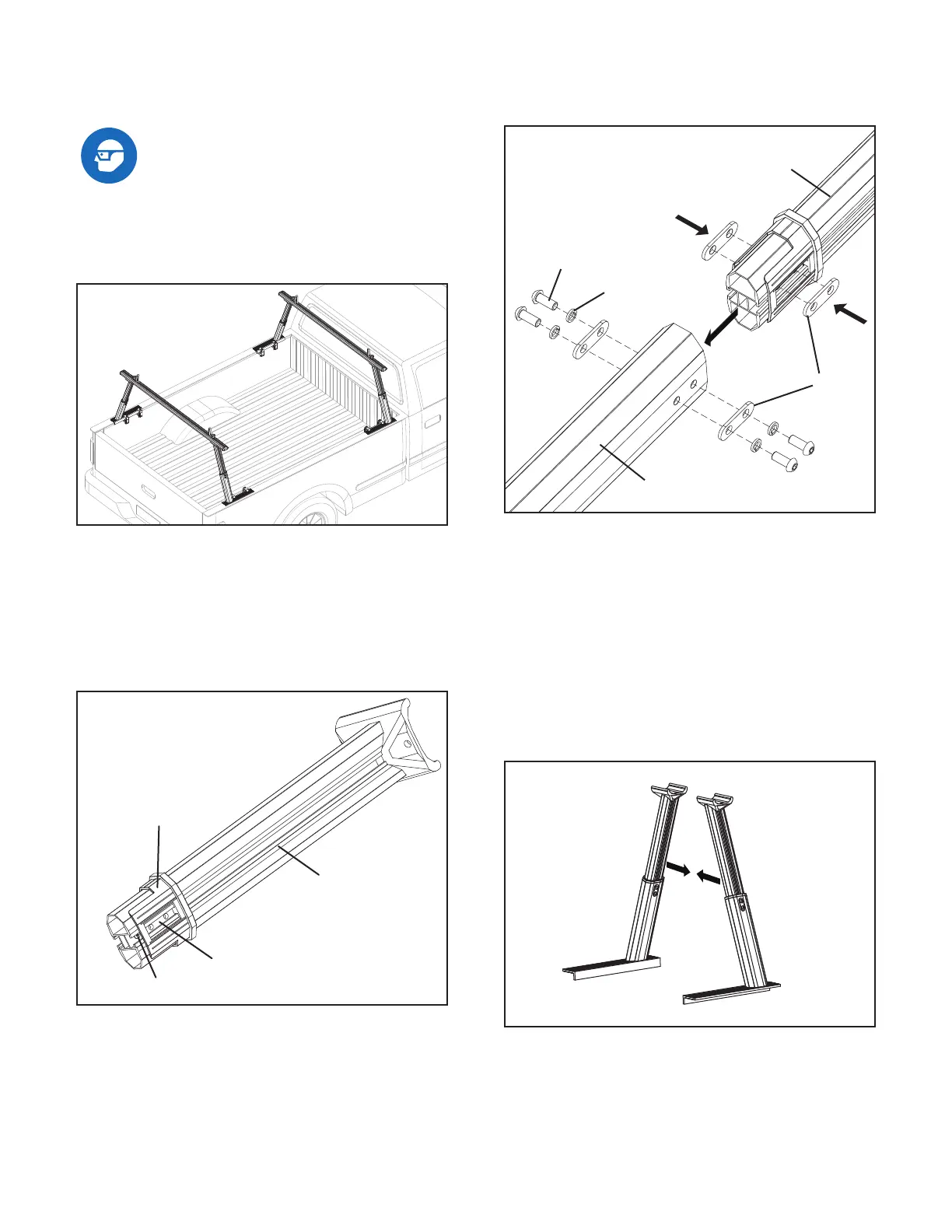
A. Assemble the Product
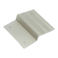
1. Take out 1 Post Component consisting of 1
Post (C), 1 Sleeve (E) 2 Threaded Plates (F)
and 1 Self-tapping Screw (J). Double check if all
above parts are in place.
2. Insert 2 Gaskets (G) into the square shaped
space in the Post Component, then insert the
whole Post Component (with 2 Gaskets (G)
inserted) into the open end of a Foot A (D1).
Connect Foot A (D1) and Post Component by 2
Gaskets (G), 4 Spring Washers (H) and 4 Bolts
(I).
3. Take out another Post Component and con-
nect it with Foot B (D2) by 2 Gaskets (G), 4
Spring Washers (H) and 4 Bolts (I).
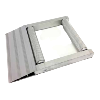
Note#1:
The two Uprights that you assembled in above
step 2 and step 3 should lean against each
other, and the shorter edge of L-shape plate of
Foot A and Foot B should be at the inner side.
See below pictures.
Note#2:
Height of all Uprights must be same. You can
adjust their heights by loosing Bolts (I), adjust to
suitable positions then tighten the Bolts (I) again.
Post Component
G
D1
I
H
Model 50613 / 50620 Page 4
 Loading...