8-12
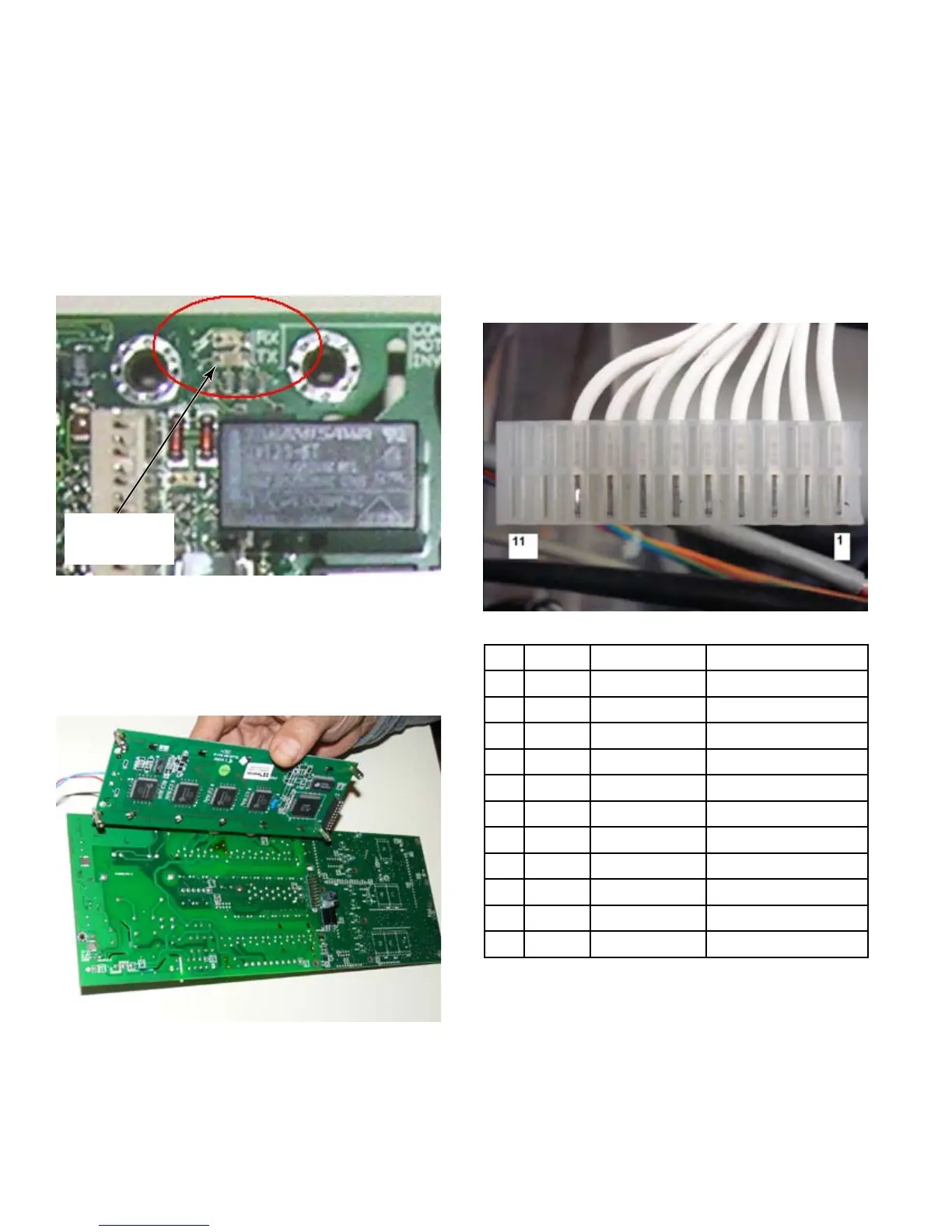
If the RX and TX LEDs are not lit then the
micro processor chip may be installed
improperly or a chip with the wrong software
is installed. It is also possible that the wrong
Machine Type was set in the Program mode
Initialization menu.
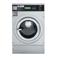
If replacing a failed control board that
has a good display, Maytag recommends
removing the display and saving it for
possible use on another washer with a
display board problem. To remove the
display board see step #5.
7.
8.
LED
Segments
R1 - HARNESS PLUG
Output Pins on control board are numbered
1 – 11 right to left as looking at the plug
from above and from the front of the
washer.
The corresponding wires on R1 plug are
shown and the readings are shown below:
Pin Wire # Resistance Connects To
1 30 3, 700 Ω Inlet Valve 1
2 32 3, 700 Ω Inlet Valve 2
3 20 3, 700 Ω Inlet Valve 3
4 42 3, 700 Ω Inlet Valve 4
5 35 3, 700 Ω Inlet Valve 5
6 46 3, 700 Ω Inlet Valve 6
7 58 110 Ω Drain Valve #1
8 53 505 Ω Contactor
9 37 Innity (N/C) Steam Valve
10 NA Innity (N/C) Drain Valve #2
11 NA Innity (N/C)
1.
2.



 To Next Page