Do you have a question about the Maytag MFR80 and is the answer not in the manual?
Provides essential safety information and precautions for operating the washing machine.
Explains the meaning of buttons, symbols, and labels used in the machine's interface and manual.
Provides an overview of the MCG Wash Computer's features, display information, hardware, and software.
Details how to access and navigate the Service - Set-Up mode for machine configuration and diagnostics.
Explains how wash programs are built step-by-step, including Wash/Rinse and Drain/Spin sequences.
Covers programming limits, water temperature, water level, extraction speed, supplies, and sequence time.
Configures general pricing options like coin values, regular and special cycle prices, and payment methods.
Enables setting special prices based on day of the week and specific time periods.
Allows setting prices based on water temperature (Hot, Warm, Cold) for regular and special cycles.
Configures upgrade options like 'Super Cycle', 'Deluxe Cycle', and 'Ultimate Cycle' with associated prices.
Guides through setting up language, water temperature, fill times, and overfill detection.
Details machine setup, including machine type, factory resets, and inverter parameters.
Allows editing individual wash programs, step-by-step, by selecting wash functions.
Explains how to modify time, water temperature, water level, and spin speed for wash cycle steps.
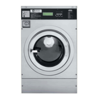
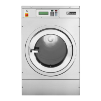
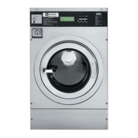
Covers initial setup steps, ensuring proper installation and key switch position before operation.
Details how the display indicates readiness and shows cycle prices when the machine is powered on.
Instructions on how to open the door, load laundry, and securely close the door.
Guide on adding detergent and softener to the correct compartments of the soap dispenser.
Explains the payment process using coins or debit cards to initiate cycle selection.
Describes how to select and start a wash cycle using the cycle buttons after loading and payment.
Explains how the display shows the remaining cycle time and progress.
Details how to pause, advance to the next sequence, or terminate a running wash cycle.
Explains how total wash time is calculated, including programmed time and extra times.
Describes the completion of a wash cycle, door unlocking, and machine readiness for the next cycle.
Explains how water is filled, measured, and temperature is controlled during the wash cycle.
Describes scenarios where the machine enters a wait state due to power interruption or safety sequences.
Explains how failure messages are displayed, their codes, and safety precautions when water is present.
Details how the machine behaves during power interruptions and how to restart cycles.
Explains how to check the current cycle status, water temperature, and water level for diagnostics.
Defines codes and symbols used for water inlet valves, water levels, and tub actions (RPM).
Details specific steps, valves, temperatures, water levels, and times for various wash cycles.
Explains various messages that may appear on the display during machine operation or errors.
Describes how fault messages are displayed, including program number, step, and diagnostic codes.
Provides guidance on overruling fault messages, safety precautions, and specific procedures for fault types.
Lists diagnostic codes, their failure descriptions, actions, and fault occurrence scenarios.
Explains how to navigate to the Service Menu from the Main Menu using the service key and ENTER button.
Allows viewing the last 20 diagnostic fault messages stored in the EEPROM memory.
Procedure to erase all fault messages from memory, typically done via YES and ENTER.
Provides accumulation of diagnostic messages over time and can be reset with the cycle counter.
Supports technical intervention by providing access to input states, pulley ratio, and service counts.
Enables verification of electrical signals into the wash computer by checking input states (On/Off).
Allows checking the motor and drum pulley ratio for correct sizing, displayed as a fixed value.
Resets service counts to inform the operator about preventive maintenance and reset diagnostic statistics.
Details managing the cycle counter, resetting escrow, and selecting model codes for future options.
Lists the sequence of tests performed in the diagnostic program, including display, sensor, motor, and water tests.
Presents the parameters for a basic diagnostic wash, including sequence, supply, inlet, temp, level, action, time, and RPM.
Guides on resolving issues where the display is not illuminated or difficult to read.
Troubleshooting steps for unresponsive buttons, non-activated outputs, and programs not starting.
Addresses problems related to the wait state counter and the 'Unload' message with an open door.
Troubleshooting for incorrect water levels and issues with the drum not turning.
Explains the D1 error code for a defective level sensor, its causes, and how to diagnose.
Details the D2 error for a faulty temperature sensor, including checks and potential PCB replacement.
Explains the D3 warning for service due, indicating the cycle counter has reached its limit.
Describes the D4 error for door switch malfunction, stopping functions when the door isn't closed.
Addresses D5 error for coin drop 1 blockage, often due to a full coinbox interrupting the sensor.
Explains D6 error when the door solenoid switch fails to open, indicating a potential safety issue.
Details D7 error for slow water filling, relating to fill time, valve issues, or sensor hose problems.
Covers D8 error for failure to drain water within the specified time, checking drain tube and valve.
Explains D10 error if the door solenoid switch is not closed, leading to immediate function stoppage.
Describes D11 error for no communication between timer and inverter, checking machine type and baud rate.
Details D12 error when the frequency inverter alarms, checking machine type and parameters.
Covers D11-D12 errors related to motor issues like spinning at low RPM, shaking, or belt slipping.
Addresses D13 error for coin drop 2 blockage, similar to D5, usually caused by a full coinbox.
Explains D14 error when the door is not locked at start, preventing cycle initiation.
Details D15 error for overfilling, related to water level exceeding programmed limits or steam heating.
Describes D16 error for communication failure with the debit card reader, cleared when communication is restored.
Explains D17 error related to the bimetal/spring security for door lock, checked each cycle.
Covers D18 errors indicating issues with the EPROM, suggesting program reload or checking for electrical noise.
Addresses D19 errors, stating that software errors should not occur and to inform the manufacturer.
Details H50 error when water temperature exceeds target by 27°F, checked via STATUS-menu.
Explains H51 error when water level rises above the overflow tube, checking tube and valve blockages.
Addresses H52 error related to tilt switch wiring on MFR machines, requiring input to stay low.
Covers H53/H54 errors for incorrect machine type selection (MFR18/MFR25), requiring correct selection.
Notes H55 as an informative code for slow refilling after initial fill, referring to D7 for evaluation.
Describes H56 error when the internal clock fails, disrupting time calculations and pricing functions.
Details H57 error for MFR18/25 when no feedback speed signal from the motor drive occurs during spin.
Covers H58/H59 errors where the door lock is engaged but the door is open, requiring technical intervention.
Notes H60 as an error that should not occur, advising to inform the manufacturer.
Explains H61 error for THT fault in frequency inverter due to over current, requiring parameter checks.
Details H62 error for OV3 fault in frequency inverter due to over voltage during deceleration, checking load and parameter.
Covers H63 error during inverter parameter writing, warning against use with incorrect settings.
Details H64 error checking inverter parameter loading, suggesting power cycling or parameter reload.
Explains H65 indicating stall prevention activation due to overload or imbalance, logged in error register.
Addresses H66 error for incorrect voltage range selection in configuration, requiring plate matching.
Covers H67 error detecting incorrect inverter model type, requiring correct selection in configuration.
Groups H71, H74, H75, H76, H88 codes for disturbed communication between card reader and wash computer.
Details E35 error for incompatible software versions, requiring reconfiguration and factory settings reset.
Provides instructions for cleaning buttons with a damp cloth after power disconnection, avoiding harsh chemicals.
Specifies essential data like software version, date, serial number, and order code needed for inquiries.
Illustrates the programmer circuit board, detailing components like flash memory, relays, and interfaces.
Step-by-step instructions for replacing the electronic board, including safety precautions and reconnection.
Guides on updating software, including clearing diagnostic messages and resetting factory settings.
Lists machine type, serial number, voltage, water supply, and programmer details.
Details data entered for machine type, brightness display, and temperature settings.
Lists data entered for language, compartment flush, hot water temperature, fill time, and overfill detection.