10
It is important that gas pressure regulators meet applicable
pressure requirements, and that gas meters be rated for the
total amount of all the dryer Btu being supplied.
For ease of service, the individual gas supply line of each dryer
must have its own manual shutoff valve.
The dryer must be isolated from the gas supply piping system
by closing its individual manual shutoff valve during any
pressure test of the gas supply system at test pressures equal to
or less than 1/2 psig (3.5 kPa).
The dryer and its individual shutoff valve must be disconnected
from the gas supply piping system during any pressure testing
of that system at test pressures in excess of 1/2 psig (3.5 kPa).
Failure to isolate or disconnect the dryer from supply as noted
can cause irreparable damage to the gas valve, voiding the
warranty.
NOTE: Undersized gas piping will result in ignition problems,
slow drying, and increased use of energy.
The input ratings shown on the data label are for elevations up
to 2,000' (610 m), unless elevation requirements of over 2,000'
(610 m) were specied at the time the dryer order was placed
with the factory. The adjustment or conversion of dryers in the
eld for elevations over 2,000' (610 m) is made by changing
each burner orice. If this conversion is necessary, contact the
distributor who sold the dryer or contact the manufacturer.
IMPORTANT: If connection to this dryer is made with a
exible hose, it must be suitable for the appliance category in
accordance with national installation regulations of the country
of destination, and if in doubt the installer must contact the
supplier. The manufacturer of this dryer does not recommend
the use of exible gas supply line/hose.
Pipe joint compounds that resist the action of natural, propane,
and butane gases must be used.
In the U.S.A: An individual manual shutoff valve must be
installed within 6' (1.8 m) of the dryer in accordance with the
National Fuel Gas Code, ANSI Z223.1.
In Canada: An individual manual shutoff valve must be installed
in accordance with the B149.1, Natural Gas and propane
Installation Code. It is recommended that an individual manual
shutoff valve be installed within 6' (1.8 m) of the dryer.
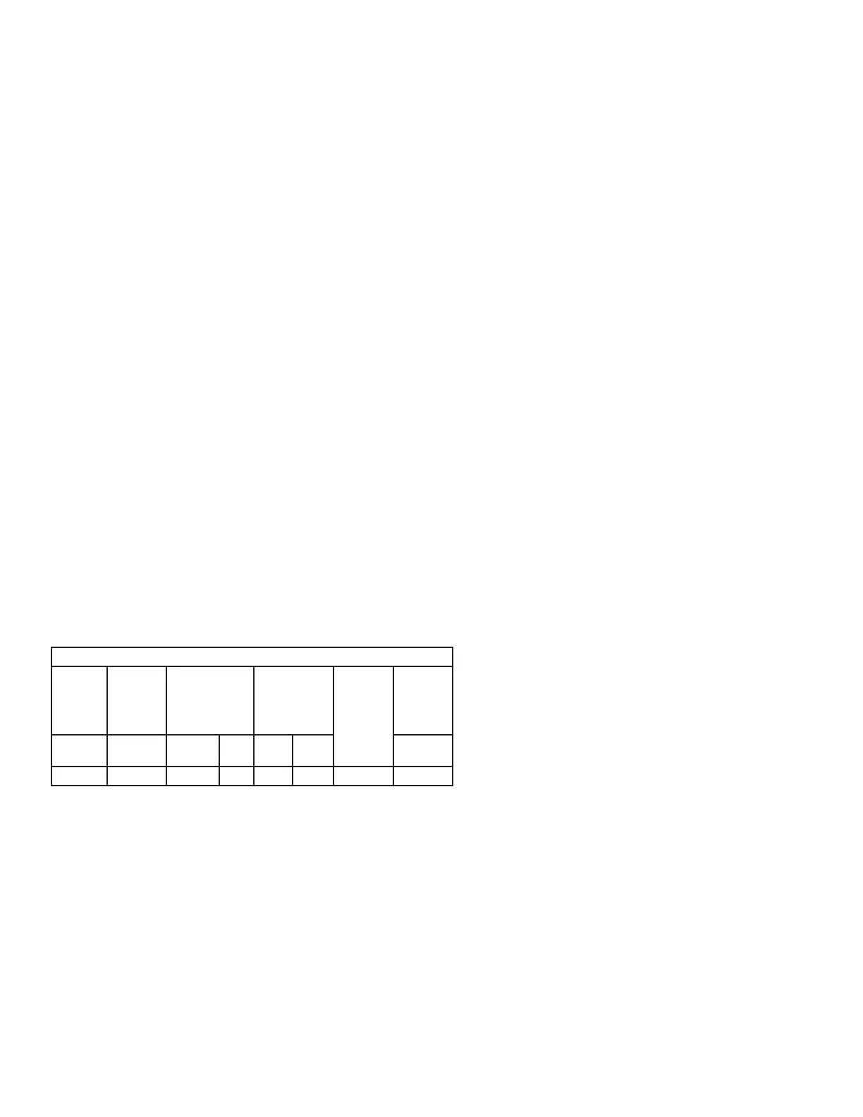
Natural Gas Specications**
Nominal
Heating
Value
Supply
Pressure
Gross Heat
Input
Orice
Size*
Orice
(Injector)
Quantity
Burner
Pressure
Btu/ft
3
in WC Btu
/hr
kW DMS mm in WC
1,000 6.0-12.0 144,000 42.2 20 4.089 2 3.5
*Consult factory for elevations over 2,000' (609.6 m) for correct burner orice
size(s).
** Btu rating for both tumblers.
Gas Connections
Inlet connection .....1/2" M.N.P.T. (1 per pocket)
Inlet supply size ....1/2" Pipe (minimum) (1 per pocket)
Combined top and bottom require a 3/4" supply (minimum)
Piping / Connections
The dryer is provided with two 1/2" N.P.T. inlet pipe connection
at the rear of the dryer. It is recommended that a gas shutoff
valve be provided to the gas supply line of each pocket for ease
in servicing.
The size of the main gas supply line (header) will vary depending
on the distance this line travels from the gas meter. Specic
information regarding supply line size should be determined by
the gas supplier.
NOTE: Undersized gas supply piping can create a low or
inconsistent pressure, which will result in erratic operation of the
burner ignition system.