Testing Procedures
!
WARNING
To avoid risk of electrical shock, personal injury or death; disconnect power to microwave oven and discharge the
high voltage capacitor before servicing, unless testing requires power.
14 16027303
© 2006 Maytag Services
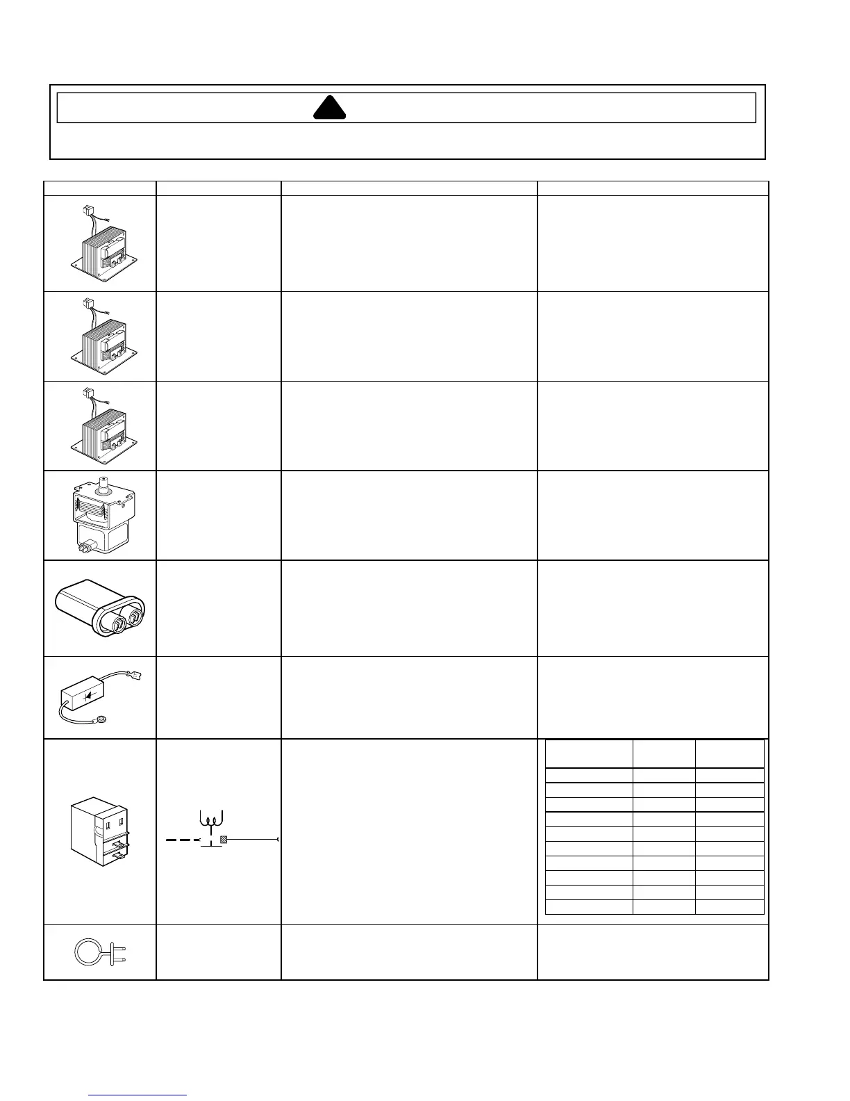
Illustration Component Test Procedure Results
Low voltage
transformer
Remove low voltage transformer from control
circuit board and check:
(Measure at room temp., or 68° F/20° C.)
Between pins 1 and 2 (Input)....................
Between pins 4 and 5 (19v output) ...........
Between pins 6 and 7 (7.0v output)..........
Between pins 7 and 8 (2.7v output)..........
Approx. 128 ..
Approx. 2 ..
Approx. 2 ..
Approx. 5 ..
Low voltage
transformer
AMV5164BC*,
MMV5165BA*
Remove low voltage transformer from control
circuit board and check:
(Measure at room temp., or 68° F/20° C.)
Between pins 1 and 2 (Input)....................
Between pins 4 and 5 (19v output) ...........
Between pins 7 and 8 (2.7v output)..........
Approx. 243 ..
Approx. 11 ..
Approx. 2 ..
Low voltage
transformer
AMV5164BA*,
AMV1154BA*,
MMV1153BA*,
UMV1152CA*
Remove low voltage transformer from control
circuit board and check:
(Measure at room temp., or 68° F/20° C.)
Between pins 1 and 2 (Input)....................
Between pins 4 and 5 (19v output) ...........
Between pins 7 and 8 (2.7v output)..........
Approx. 379 ..
Approx. 11 ..
Approx. 2 ..
Magnetron Discharge Capacitor
Remove wires from magnetron and connect
ohmmeter to terminals. Also check between
each terminal and ground.
Between Terminals: Less than 1 .
Each Terminal to Ground: Infinite ..
NOTE: This test is not conclusive. If
microwave oven does not heat and all
other components test good, replace the
magnetron and retest.
High Voltage
Capacitor
Discharge Capacitor
Remove wires from capacitor terminals and
connect ohmmeter, set on highest resistance
scale to terminals.
Check resistance between each terminal and
capacitor case. ..................................................
Between Terminals: Meter should
momentarily indicate continuity, then 9
M (deflection). A steady 9 M indicates
an open capacitor. Steady continuity
indicates a shorted capacitor. In either
case, replace capacitor.
Infinite .
High Voltage Diode Discharge Capacitor
Remove diode lead from capacitor and
connect ohmmeter.
Reverse leads for second test.
Infinite resistance should be measured in
one direction and several hundred K in
the opposite direction.
NOTE: Ohmmeter must contain a battery
of 6 volts minimum.
Power Control Relay
Disconnect the leads. Place water in the
microwave oven and select power levels 1
through 10. Press the START pad. Check
continuity between the terminals of the relays ...
Power Level
Cycle On
(Continuity)
Cycle Off
(Open)
1 4 sec 26 sec
2 7 sec 23 sec
3 10 sec 20 sec
4 13 sec 17 sec
5 16 sec 14 sec
6 19 sec 11 sec
7 22 sec 8 sec
8 25 sec 5 sec
9 28 sec 2 sec
10 30 sec 0 sec
Grill heater element
JMV9169BA*,
JMV8166BA*,
AMV6167BD*
Remove all wires from heater.
Measure resistance across terminals ................
Approx. 15-25 (70° F, 20° C).
 Loading...