EasyManua.ls Logo

Mazda 0000-8C-Z05 User Manual

Mazda 0000-8C-Z05
13 pages
To Next Page IconTo Next Page
Page #1 background imageLoading...
Page #1 background image
GENUINE ACCESSORIES
INSTALLATION INSTRUCTIONS
PART NUMBERS: APPLICABLE MODELS:
0000-8C-Z05 Electrochromic Mirror w/ Compass/Temp/HL 2006 > Mazda5
0000-8C-L27 Compass/Temp/HomeLink
®
Installation Kit
REQUIRED COMPONENTS:
ITEM QTY DESCRIPTION SERVICE PART NUMBER
1 1 Mirror Assembly with Compass, Temp and HomeLink
®
0000-8C-Z05
INSTALLATION KIT COMPONENTS:
2 1 Harness Assembly – Power, Battery and Ground 000-8C-H12
3 2 Wire Tap 000-8C-H09
4 3 Foam Tape --
5 1 Temperature Sensor 000-8C-G18
6 1 Harness Assembly – Temperature Sensor 000-8C-G17
7 4 Tie Wrap (Long) --
8 1 Tie Wrap (Short) --
9 1 Wire Cover 000-8C-H11
10 1 Protective Sleeve --
11 1 Installation Instructions --
12 1 User Guide --
HOMELINK
®
AND THE HOMELINK HOUSE
®
ARE REGISTERED TRADEMARKS OF JOHNSON CONTROLS, INC.
TOOLS REQUIRED:
Clean Rag
Fish Wire #T20 Torx Wire Cutters
Fiberstick
Electrical Tape Ratchet Phillip's Screwdriver
Pliers
4mm Flat Screwdriver 10mm Socket
Page 1 of 13 Revision A 550-0339
Question and Answer IconNeed help?

Do you have a question about the Mazda 0000-8C-Z05 and is the answer not in the manual?

Mazda 0000-8C-Z05 Specifications

General IconGeneral
BrandMazda
Model0000-8C-Z05
CategoryAutomobile Accessories
LanguageEnglish

Summary

Preparation

Disconnect negative battery terminal

Safely disconnect the vehicle's negative battery terminal to prevent electrical issues.

EC Mirror Installation

Attach EC mirror

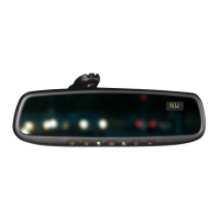
Mount and secure the new EC mirror onto the windshield button.

Temperature Sensor Harness Installation

Complete Installation of Temperature Probe Wires

Connect temperature harness to 10-pin connector

Connect the temperature harness terminals to the 10-pin power connector.

Route Harness to Vehicle Power

Plug 10-pin connector into back of EC mirror

Connect the main 10-pin harness connector to the rear of the EC mirror.

Connect Harness Power and Ground

Attach wire tap connectors to B+ and +12V ignition

Connect wire taps to the vehicle's B+ and +12V ignition wires.

Connect EC power harness to ground

Connect the EC power harness ground ring to the vehicle's chassis.

Connect EC power harness to B+ wire tap

Connect the EC power harness to the B+ wire tap.

Connect EC power harness to +12V ignition

Connect the EC power harness to the +12V ignition wire tap.

Testing

Reconnect negative battery cable

Reconnect the vehicle's negative battery terminal.

Turn ignition switch ON/ACC

Turn the vehicle ignition switch to the ON or Accessory position.

Verify auto-dimming and display features

Test auto-dimming by covering photocell, and verify display content.

Related product manuals