ENGINE
3.
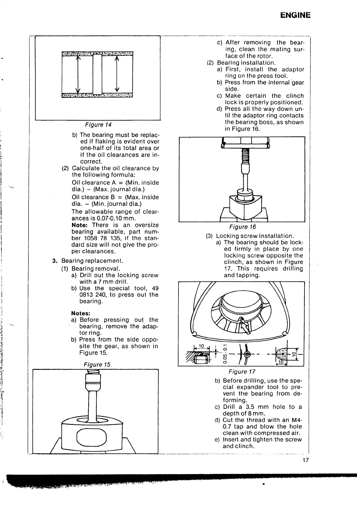
b) The bearing must
be
replac-
ed if flaking is evident
over
one-half of its total
area or
if
the oil
clearances are
in-
correct.
(2)
Calculate the oil clearance
by
the following formula:
Oil
clearance
A
= (Min.
inside
dia.)
-
(Max.
journal
dia.)
Oil clearance B
=
(Max.
inside
dia.
-
(Min.
journal
dia.)
The
allowable
range
of
ances
is
0.07-0.10
mm.
Note:
There
is
an oversize
bearing available,
parl
num-
ber 1058 78
135, if
the stan-
dard size will
not
give
the
pro-
per
clearances.
Bearing
replacement.
(1)
Bearing removal.
a) Drill out the locking screw
withaTmmdrill.
b)
Use
the
special
tool, 49
0813 240,
to
press
out
the
bearing.
Notes:
a) Before
pressing
out the
bearing,
remove the
adap-
tor ring.
b) Press from the side oppo-
site the
gear,
as shown
in
Figure 15.
Figure 15
c) After
removing
the
bear-
ing,
clean the mating
sur-
face
of
the rotor.
(2)
Bearing installation.
a) First, install the
adaptor
ring
on the
press
tool.
b) Press from
the
internal'gear
side.
c)
Make certain the
clinch
lock is
properly positioned.
d) Press
all
the
way down
un-
til
the adaptor ring contacts
the bearing
boss, as
shown
in Figure 16.
Figure 16
(3)
Locking screw installation.
a)
The
bearing should be
lock-
ed firmly in
place
by one
locking
screw opposite
the
clinch, as shown
in Figure
17. This
requires
drilling
and
tapping.
Figure 17
b)
Before
drilling,
use
the spe-
cial expander
tool
to
pre-
vent
the bearing from de-
forming.
c) Drill a 3.5
mm hole to
a
depth of 8
mm.
d) Cut the thread with an M4-
0.7
tap
and blow the
hole
clean
with compressed
air.
e) Insert and tighten the screw
and
clinch.
i
J
l;
.-
il
,t
:l
.{
,I
-t
l!
d
.!
.t
I
,.i
i1
i"{
,i
.t
ti
iii
,i
,l
t
'i
17
Figure l4