ENGINE
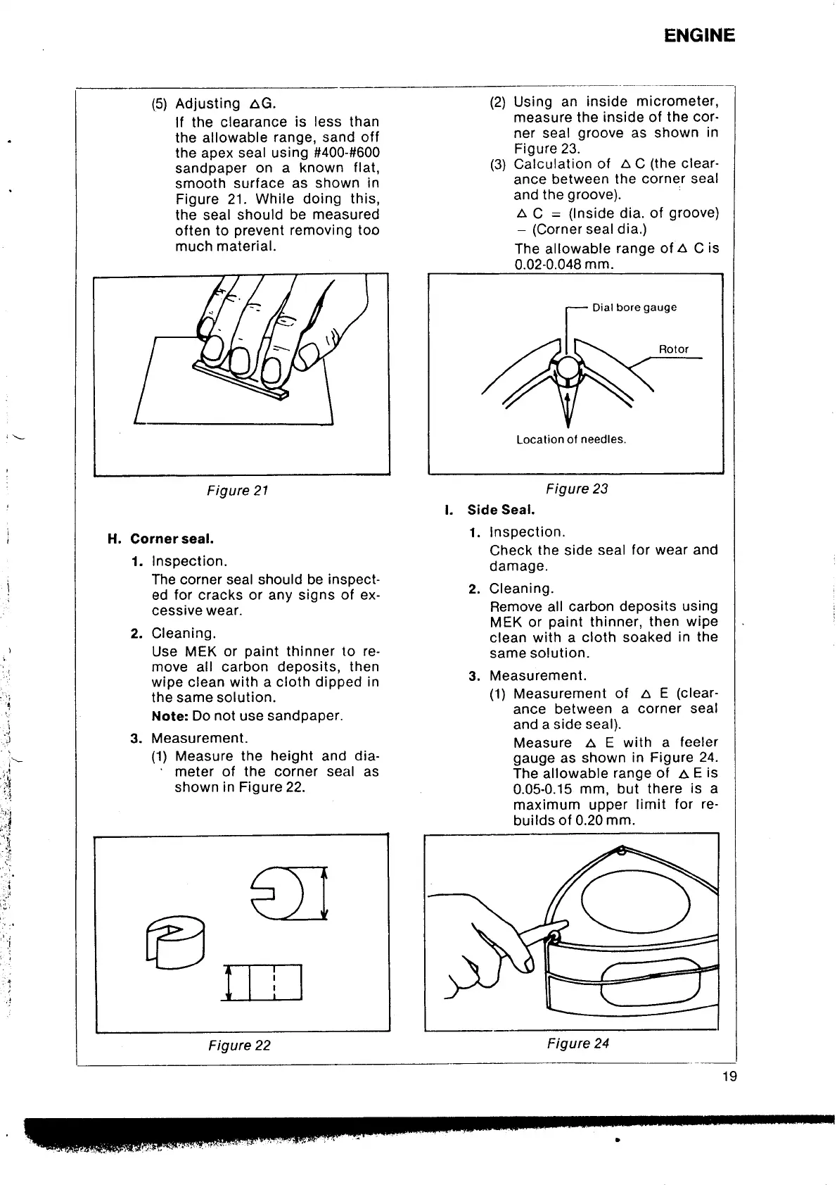
(5)
Adjusting aG.
lf the
clearance
is
less
than
the allowable
range, sand
off
the apex seal using
#400-#600
sandpaper
on a known
flat,
smooth
surface as
shown
in
Figure 21.
While doing
this,
the seal should
be
measured
often
to
prevent
removing too
much material.
H.
Corner
seal.
1. Inspection.
The corner seal should be
inspect-
ed for cracks or any signs
of
ex-
cessive wear.
2. Cleaning.
Use MEK
or
paint
thinner
to re-
move all carbon deposits,
then
wipe clean with a cloth dipped
in
the same solution.
Note: Do not use sandpaper.
3. Measurement.
(1)
Measure the
height
and
dia-
'
meter of the corner seal as
shown
in
Figure 22.
Using
an
inside
micrometer,
measure
the inside of
the cor-
ner seal
groove
as shown
in
Figure 23.
Calculation
of
A
C
(the
clear-
ance between
the
corner seal
and
the
groove).
A
C
=
(lnside
dia. of
groove)
-
(Corner
seal
dia.)
The allowable
range of
a
C
is
0.02-0.048
mm.
Dial
bore
gauge
Location
of
needles.
Figure
23
l. Side
Seal.
1. Inspection.
Check
the
side
seal
for wear and
damage.
2. Cleaning.
Remove
all carbon
deposits
using
MEK
or
paint
thinner,
then wiPe
clean with a
cloth soaked
in
the
same solution.
3. Measurement.
(1)
Measurement
of a E
(clear-
ance between
a
corner seal
and
a side seal).
Measure
aEwithafeeler
gauge
as
shown
in Figure 24-
The allowable
range of
a
E
is
0.05-0.15
mm, but there
is
a
maximum upper
limit
for
re-
builds
of 0.20
mm.
(2\
(3)
i
.l
t
rll
,
:,1
tl
.'rii
'.
l
.rl
r;
".i:
1;l
't
-:i
,,
;
,i
t.;i
';;
'l
€I
P
\--
ill_]
Figure
22