11
Power Supplies—PWR B (optional, and can be purchased separately). Power supply B is a hot-swappable,
redundant power supply. This power supply also uses a standard IEC320-C13 port, and you can use the
McAfee--provided cable or acquire one that meets your specic needs.
12
Five Back panel LEDs. The LEDs which indicate the Sensor's fan and power supply operational status.
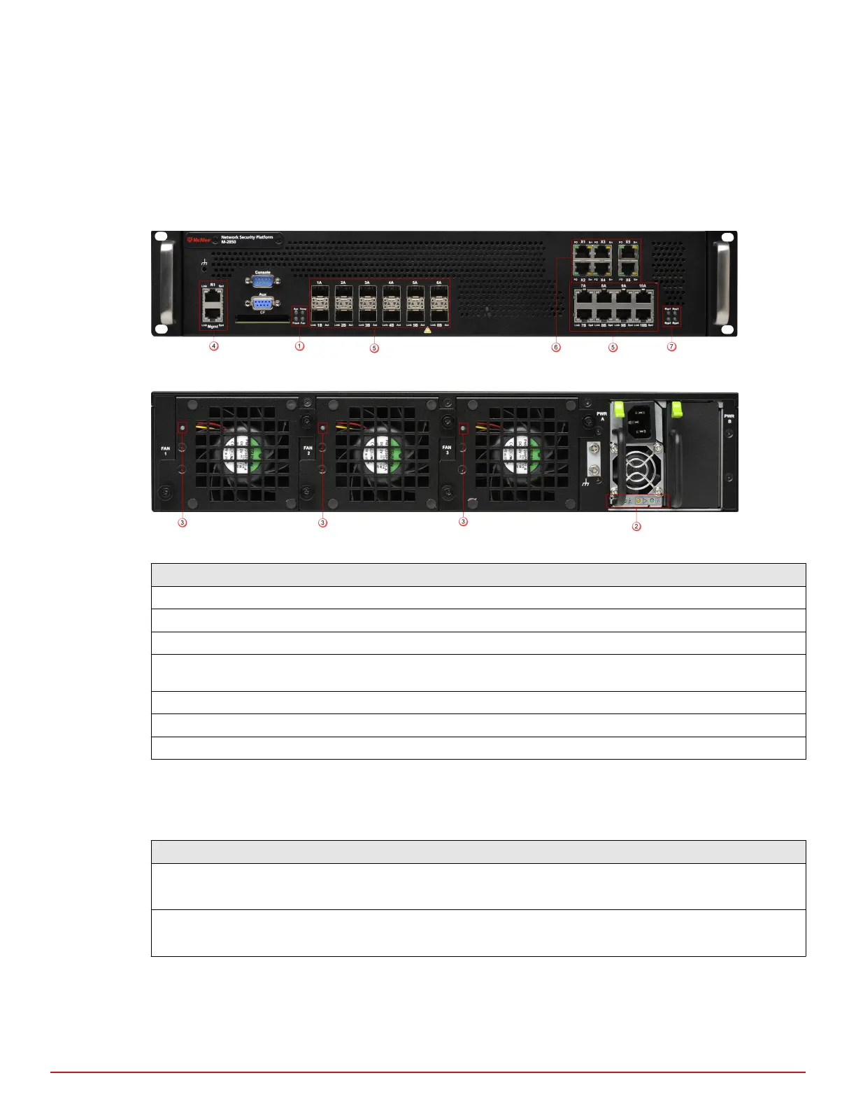
Front and back panel LEDs
Figure 1-3 Front panel LEDs
Figure 1-4 Back panel LEDs
Region in the image LEDs represented here
1 Sys, Temp, Flash, Fan
2 Power A
3 Back panel fan LEDs
4 Management Port Speed, Management Port Link, Response Port Speed, Response Port
Link
5 Gigabit Ports (SFP) Act, Gigabit Ports (SFP) Link
6 Fail-Open Control Port FO, Fail-Open Control Port Err
7 Bypass LEDs
The front panel LEDs provide status information for the health of the Sensor and the activity on its ports. The
back panel LEDs provide information regarding the Sensor fans and the power supply.
The following tables describe the front and back panel LEDs of M-2850/M-2950:
LED Status Description
Sys Green
Amber
Sensor is operating.
Sensor is booting. (It could also indicate a system failure.)
Temp Green
Amber
Inlet air temperature measured inside chassis is normal. (Chassis temperature OK.)
Inlet air temperature measured inside chassis is too hot. (Chassis temperature too hot.)
1
Introducing Network Security Sensors
M-2850/M-2950 physical description
10
McAfee
®
Network Security Platform M-2850/M-2950 Sensor Product Guide