OPERATION
cu'n'ING HEIGHT ADJUSTMENT
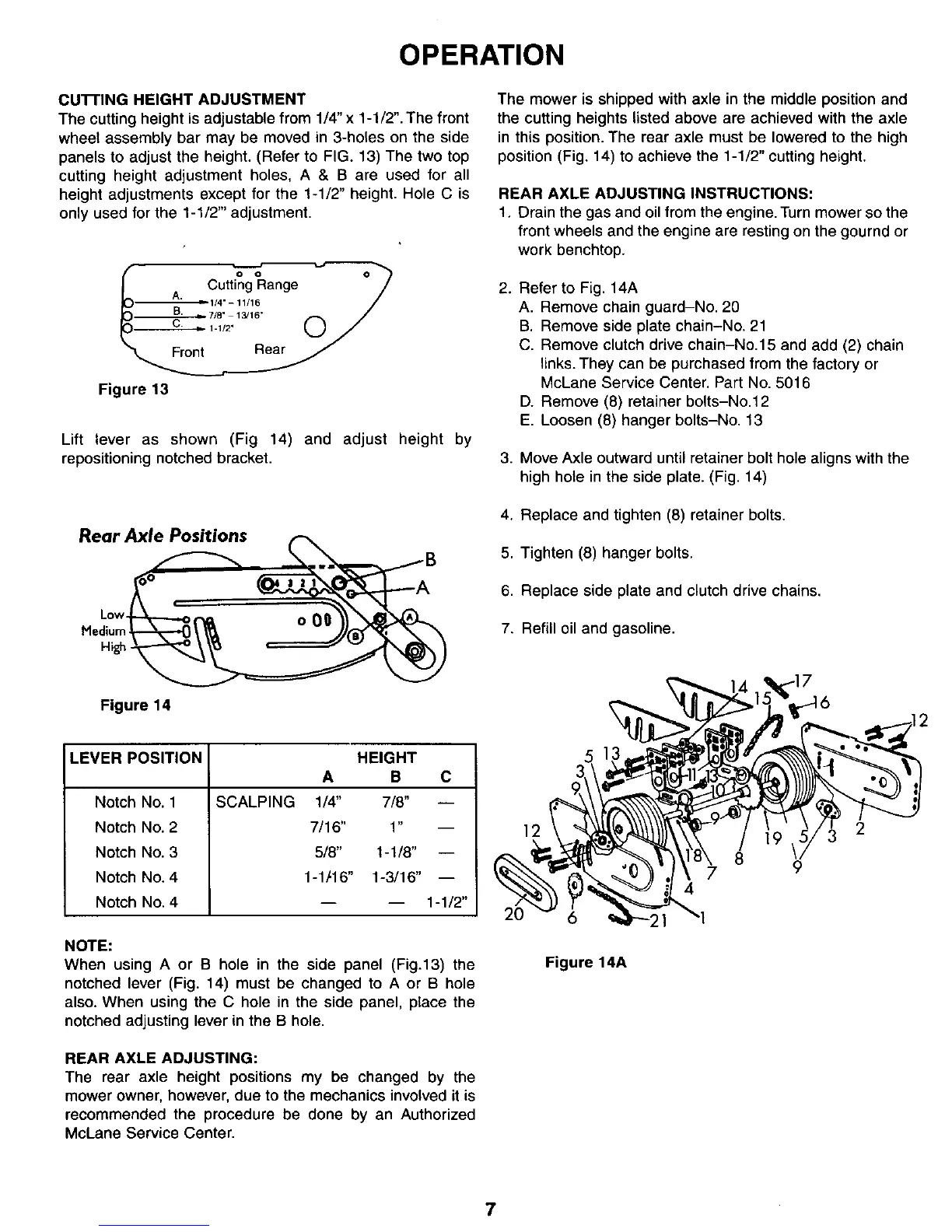
The cutting height is adjustable from 1/4" x 1-1/2". The front
wheet assembly bar may be moved in 3-holes on the side
panels to adjust the height. (Refer to FIG. 13) The two top
cutting height adjustment holes, A & B are used for all
height adjustments except for the 1-1/2" height. Hole C is
only used for the 1-t/2"' adjustment.
Cutt_
A. 1/4"-11/16
F o/
Figure 13
Lift lever as shown (Fig 14) and adjust height by
repositioning notched bracket.
Rear Axle Positions
o.
Figure 14
LEVER POSITION
SCALPINGNotch No. 1
Notch No. 2
Notch No. 3
Notch No. 4
Notch No. 4
HEIGHT
A B C
1/4" 7/8" i
7/16" 1" --
5/8" 1-1/8" --
1-1t16" 1-3/16" --
-- -- 1-1/2"
NOTE:
When using A or B hole in the side panel (Fig.13) the
notched lever (Fig. 14) must be changed to A or B hole
also. When using the C hole in the side panel, place the
notched adjusting lever in the B hole.
REAR AXLE ADJUSTING:
The rear axle height positions my be changed by the
mower owner, however, due to the mechanics involved it is
recommended the procedure be done by an Authorized
McLane Service Center.
The mower is shipped with axle in the middle position and
the cutting heights listed above are achieved with the axle
in this position. The rear axle must be lowered to the high
position (Fig. 14) to achieve the 1-1/2" cutting height.
REAR AXLE ADJUSTING INSTRUCTIONS:
1. Drain the gas and oil from the engine. Turn mower so the
front wheels and the engine are resting on the gournd or
work benchtop.
2.
Refer to Fig. 14A
A. Remove chain guard-No. 20
B. Remove side plate chain-No. 21
C. Remove clutch drive chain-No.15 and add (2) chain
links. They can be purchased from the factory or
McLane Service Center. Part No. 5016
D. Remove (8) retainer bolts-No.12
E. Loosen (8) hanger bolts-No. 13
3. Move Axle outward until retainer bolt hole aligns with the
high hole in the side plate. (Fig. 14)
4. Replace and tighten (8) retainer bolts.
5. Tighten (8) hanger bolts.
6. Replace side plate and clutch drive chains.
7. Refill oil and gasoline.
12
8
7
4
9
2
Figure 14A
7