IOMM AGR AGR 055A through 100A 67
Controller Inputs /Outputs
Analog Inputs
Analog inputs are used to read the various temperatures and pressures on the chiller as well as any
customer supplied 4-20mA reset signals. The controller’s internal regulated 5 Vdc and 12 Vdc
supplies provide correct operating voltage for the sensors. See Table 19 for details.
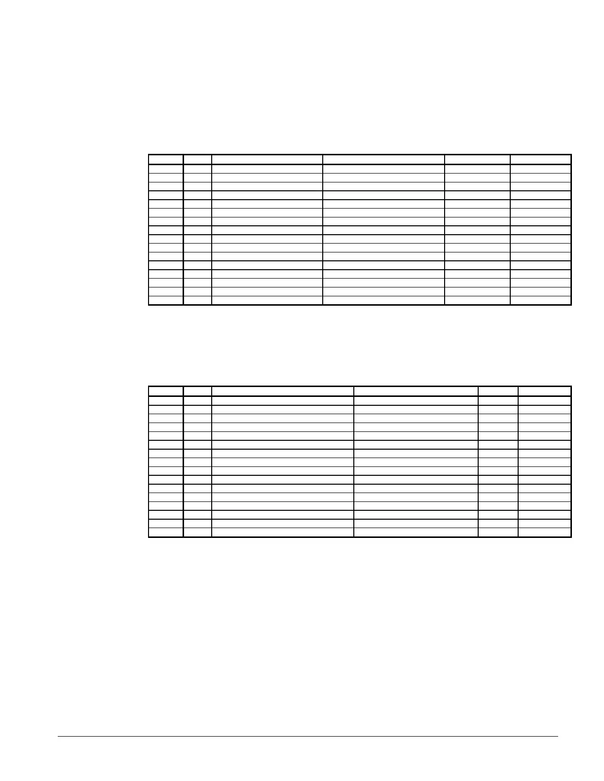
Table 19, Analog Inputs
Input LED Description Location Range Resolution
0 0 Leaving Chilled Water Temp Leaving Chw nozzle -40 to 263°F 0.1°F
1 1 Circuit #1 Evap Pressure Circuit #1 Suction Line 0 to 145 psi 0.1 psi
2 2 Circuit #2 Evap Pressure Circuit #2 Suction Line 0 to 145 psi 0.1 psi
3 3 Circuit #1 Cond Pressure Compressor Discharge Line- 20 to 450 psi 0.5 psi
4 4 Circuit #2 Cond Pressure Compressor Discharge Line- 20 to 450 psi 0.5 psi
5 5 Voltage Ratio Signal EnGinn Power Supply 4.1 to 5.1 Vdc --
6 6 Chw Water Reset Supplied by others 4 to 20 mA DC --
7 7 Demand Limit Signal Supplied by others 4 to 20 mA DC --
8 8 Entering Evap Water Temp Entering Chw Nozzle -40 to 263°F 0.1°F
9 9 Entering Cond Water Temp Enter Cond Water Nozzle -40 to 263°F 0.1°F
10 10 Leaving Cond Water Temp Leaving Cond Water Nozzle -40 to 263°F 0.1°F
11 11 % Total Unit Amps Control Cabinet 0 to 4 Vdc --
12 12 Circuit #1 Suction Temp Circuit #1 Suction Line -40 to 263°F 0.1°F
13 13 Circuit #2 Suction Temp Circuit #2 Suction Line -40 to 263°F 0.1°F
14 14 Circuit #1 Liquid Line Temp Circuit #1 Liquid Line -40 to 263°F 0.1°F
15 15 Circuit #2 Liquid Line Temp Circuit #2 Liquid Line -40 to 263°F 0.1°F
Digital Inputs
All Digital Inputs are 24 Vac. At 7.5 Vac to 24 Vac the digital input contacts are considered closed.
Below 7.5 Vac, the contracts are considered open. See Table 20 for details and operating
characteristics.
Table 20, Digital Inputs
Input LED Description Circuit Closed Open
0 0 Mechanical High Pressure Switch Circuit #1 Normal Alarm
1 1 Oil differential switch Compressor #1 normal Alarm
2 2 Motor Protection Switch Compressor #1 Normal Alarm
3 3
4 4
5 5 System Switch Unit Run Stop
6 6 Phase/Voltage Monitor Unit Normal Alarm
7 7 Pumpdown Switch Unit Pmp Dn Normal
8 8 Mechanical High Pressure Switch Circuit #2 Normal Alarm
9 9 Oil Differential Switch Compressor #2 Normal Alarm
10 10 Motor Protection Switch Compressor #2 Normal Alarm
11 11
12 12
13 13 Chiller Remote Stop Switch Unit Run Stop
14 14 Evap Water Flow Switch Unit Run Stop
15 15 Pumpdown Switch Circuit #2 Pmp Dn Normal
Relay Board Outputs
All of the MicroTech panel outputs are controlled by solid-state relays which are driven by the
model 250 controller. The controller activates a solid-state relay by sending a “trigger” signal to
the output board via the attached ribbon cable. The relay responds to the trigger by lowering it’s
resistance which allows current to flow through it’s “contacts”. When the controller removes the
trigger signal, the relay’s resistance becomes very high, causing the current flow to stop. The
outputs are individually protected by a 5 amp fuse mounted on the output board adjacent to each
relay. Table 21 provides additional information about each output. Refer to the MicroTech Staging
schematic for digital output wiring.
 Loading...


