98 AGR 055A through 100A IOMM AGR
3. Remove power from the controller by opening CB1. Try to improve the connections in the
Aux/Out plug insulation displacement terminals by pressing down on the wires with a small
screwdriver.
4. Check all other wiring and connectors for bent pins or mis-wires.
If the chatter does not stop, the electromechanical relay or contactor is probably defective.
Troubleshooting Solid-State Relays
As shown on the unit wiring diagrams, the Solid-State relays on the Output Boards all have
normally open “contacts.” Actually, these contacts do not exist as they do in an electromechanical
relay. Instead of using contacts to switch the load, the Solid-State relay changes its resistance from
low (closed), when it is energized, to high (open), when it is de-energized. (This high resistance is
approximately 100K ohms.) Because the output circuit through the Solid-State relay remains
continuous regardless of whether the relay is energized, troubleshooting a Solid-State relay with a
voltmeter can be tricky.
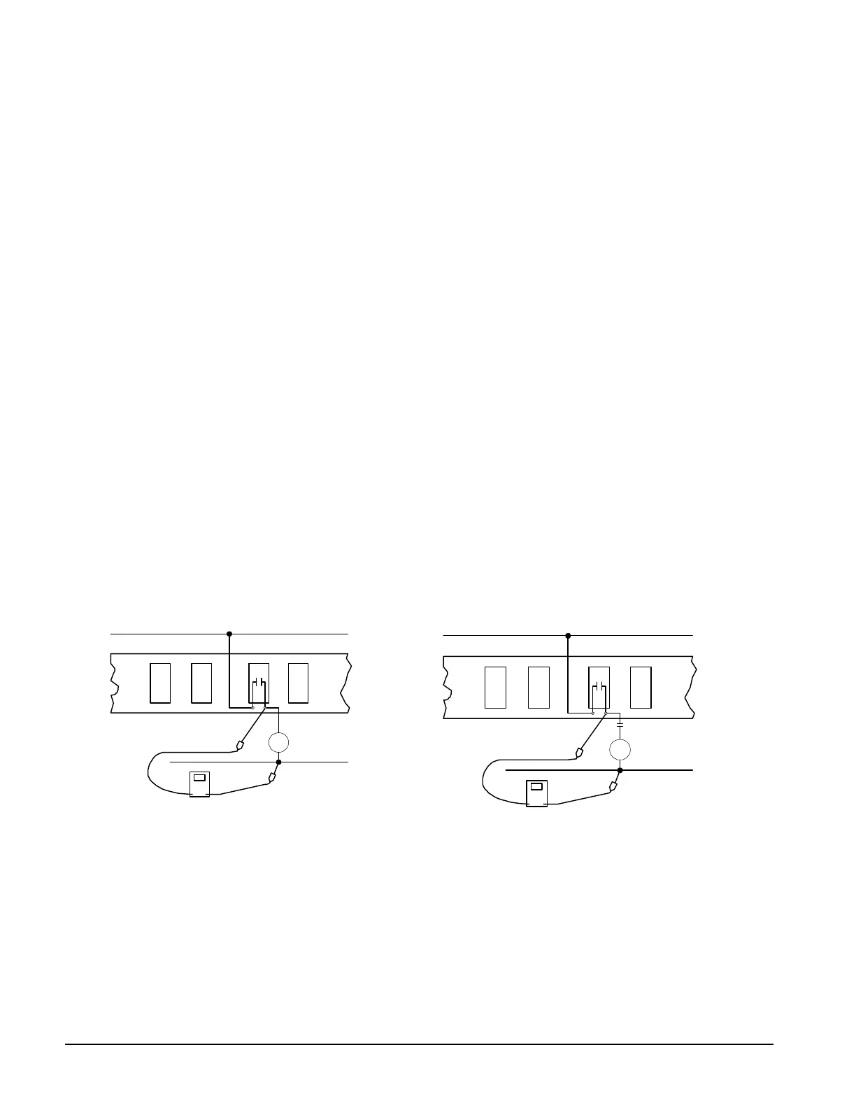
In a typical circuit, a power source is connected across a single relay output and a load. In this
circuit, a Solid-State relay will behave like an electromechanical relay. If the relay is energized, the
relay output will be hot. If the relay is de-energized, voltage cannot be measured at the relay output.
The circuit shown in Figure 40 is similar to a typical circuit; the difference is that there is an
open set of contacts, or a disconnection between the relay output and the load. In this circuit, a
Solid-State relay will not behave like an electromechanical relay. if the Solid-State relay is
energized, the relay output will be hot (as expected). However, if the Solid-State relay is de-
energized, the relay output will still appear to be hot. This is because the relay output and the
voltmeter form a continuous circuit in which the relay’s resistance, though high, is insignificant
compared to the voltmeter’s resistance.
This means that nearly all the voltage is dropped across the voltmeter. Therefore, the voltmeter
indicates that voltage is present. If a low wattage light bulb of the appropriate voltage is used instead
of a voltmeter, the bulb’s low resistance will load the circuit enough to eliminate the false voltage
indication. In this situation, an incandescent test lamp is a better tool than a voltmeter.
Figure 40, Testing a Typical Relay Circuit Figure 41, Testing a Relay Circuit with a Disconnection
M10
0V
115 VAC
Output Board
DO 13
28 27
Neutral
M10
115V
115 VAC
Output Board
DO 13
28 27
Neutral
 Loading...


