Do you have a question about the McQuay ALZ “B” and is the answer not in the manual?
Explains the manual's role for installers and operators.
Details checking the shipment, damage, and serial plate upon receipt.
Outlines McQuay Italia's disclaimer for injuries and damages.
Specifies that maintenance must be done by trained personnel.
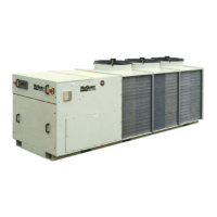
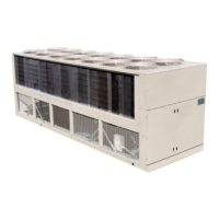
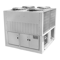
Introduces the ALZ/ALP units with scroll compressors and electronic control.
Contains electrical data like voltage, current, and power for different unit sizes.
Lists operational limits for entering/leaving water and ambient temperatures.
Provides factors to adjust cooling capacity based on altitude.
Lists correction factors for glycol concentration and low ambient temps.
Provides performance correction factors for low temperatures with ethylene glycol.
Details fouling factors and corresponding cooling capacity correction factors.
Lists physical data like capacity, power, dimensions, and weights for unit sizes.
Details compressor specifications, oil charge, refrigerant, and heat exchanger volume.
Provides information on condenser fans, motor power, and unit dimensions.
Lists essential safety rules for handling and operating the unit.
Covers installation warnings, transport, handling, and location/ventilation requirements.
Details minimum distances for condenser coil ventilation and inspection.
Mentions meeting noise regulations and ensuring insulation for special requirements.
Recommends shut-off valves, indicators, strainers, and leak checks for water piping.
Advises on measures to prevent frost damage to heat exchangers and piping.
Lists the primary control functions of the microprocessor.
Enumerates devices managed by the microprocessor.
Describes the 3-digit display and its readings.
Explains the meaning of LEDs indicating unit status.
Details how the controller signals alarm conditions.
Lists display codes, types, and reset methods for various alarms.
Details voltage supply range and power absorption.
Specifies current ratings for power connectors and relays.
Describes the microprocessor controller's integrated systems and expansion capabilities.
Identifies connection areas on the main board for power, probes, and digital inputs.
Highlights areas for serial interface, key connection, and pin-strip settings.
Details connection areas for analog inputs, digital inputs, and outputs for the second circuit.
Explains the 5 LED indicators on the terminal display for unit status.
Describes the 3-digit display and its decimal point behavior.
Defines the meaning of LEDs for compressor and unit status.
Lists actions taken when an alarm condition is detected.
Describes how the unit restores normal operation after alarms are cleared.
Lists alarm types, detection methods, and display messages.
Specifies power supply range and minimum absorbed power.
Details operating temperature, humidity, and index of protection.
Explains how to set and display direct parameters like cooling set-point.
Describes how to access and modify protected user parameters with a password.
Details how to access and modify protected factory configuration parameters.
Explains how to mute buzzer, reset alarms, and force defrosting.
Describes unit stand-by mode and how to reset operating hour timers.
Explains copying data between unit EEPROM and hardware key.
Describes how to set default parameters at startup.
Summarizes the function of SEL, PRG, and other button combinations.
Lists essential checks before starting the unit, including electrical and piping.
Outlines the step-by-step process for starting the unit by specialized personnel.
Explains how to use the emergency stop and restart the unit.
Shows overall unit dimensions and key measurements.
Illustrates the fan configurations for different model series.