304 C – 02/06 D – pag. 9/16
Main board (single tandem)
The main board represents the core of the system, where the signals coming from the probes are processed. The
modular structure of "µchiller" allows to get great flexibility and high performance. The compressor board, for
example, can be upgraded by adding a module for the regulation of the capacity-controlled routine of the
compressor or for the activation of a second tandem.
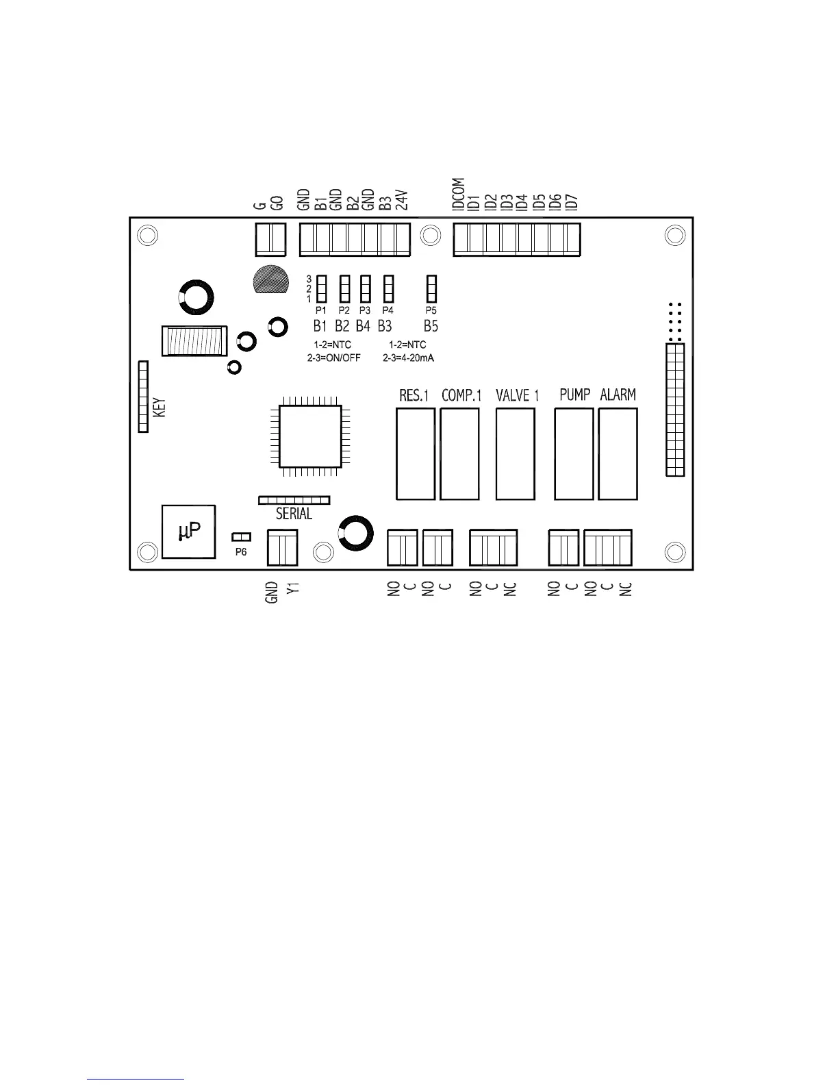
On this board you can locate clockwise the following connection “areas”:
• G and G0 terminals for power source connection (24Vac)
• analog inputs (from B1 to B3) for probe connection
• 24V terminal (with D.C.) for the supply of any pressure probes
• digital inputs (from ID1 to ID7) for alarm connection
• jumper connector for expansion board connection
• digital relay outputs to manage any controlled device
• the Y1 GND analog output for the connection of the optional boards for the management of condensation fans
(ON/OFF regulation mode or with continuous rotation speed variation)
• telephone connector for user terminal connection
Within the board itself you can also locate other four important areas:
• the SERIAL jumper for connection of an optional serial board for the interfacing to a supervisory and/or
telemaintenance centralized system
• the KEY jumper for connection of an optional board (removable hardware key) for the immediate programming
of all data
• P1÷P5 pin-strips for the function mode selection of the analog inputs (B1÷B5)
• P6 pin-strip relative to the Y1 analog output (to be normally left open, except in particular situations – see
parameters F3 and F4).
 Loading...