1-3
English
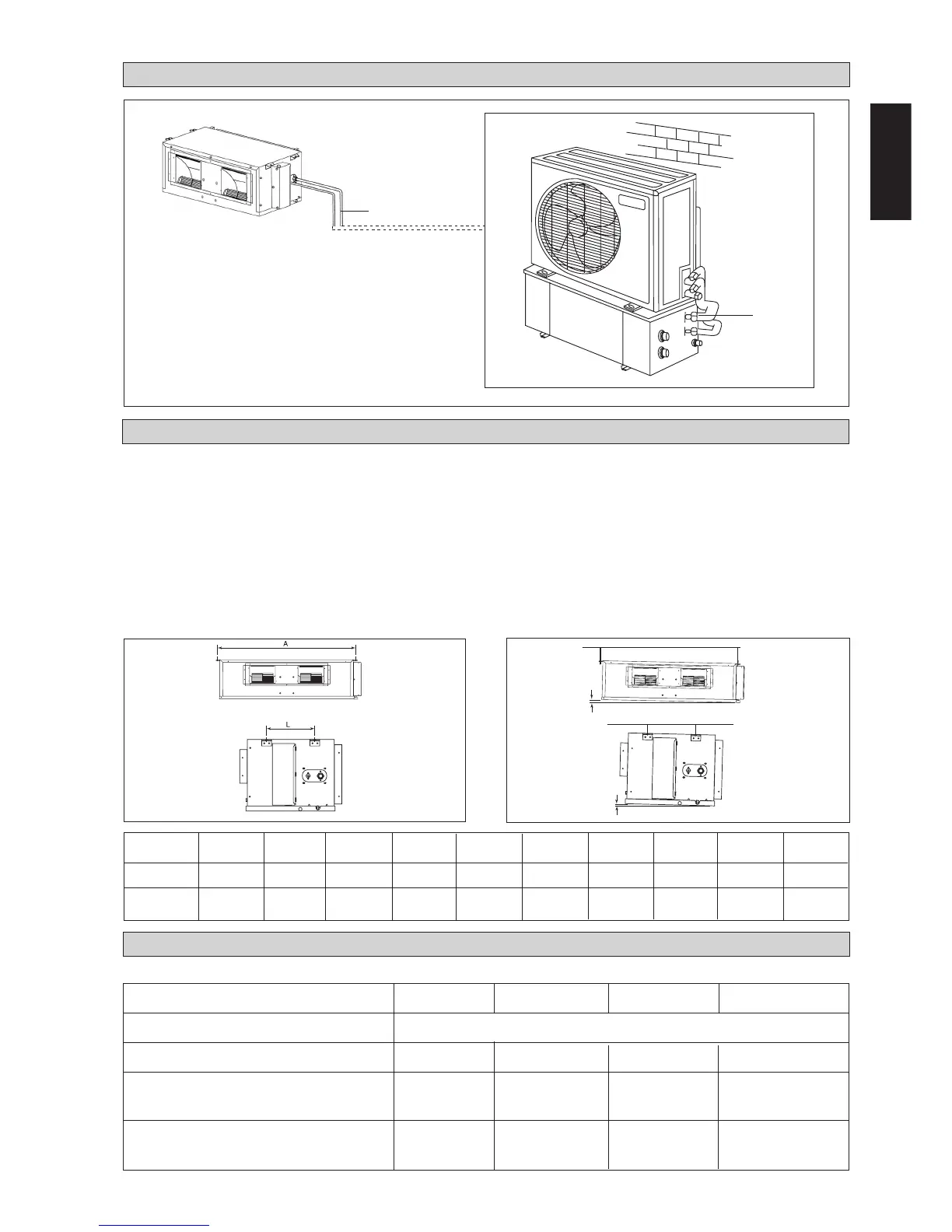
INSTALLATION OF THE INDOOR UNIT
The indoor unit must be installed such that there is no short circuit of the cool discharge. Respect the installation clearance. Do
not put the indoor unit where there is direct sunlight on unit. The location must be suitable for piping and drainage and it must
have a large distance between a door and unit.
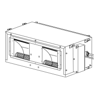
CEILING CONCEALED MOUNTING
– Use the hanger supplied with the unit.
– Make sure that the ceiling is sufficiently strong to withstand the weight.
Center distance of axle (see drawing below) Provide clearance for servicing ease and optimal air flow as
shown in the diagram.
INSTALLATION DIAGRAM
WATER PIPING
CHILLER
OUTDOOR UNIT
INDOOR UNIT
CC 10 CW 15 CW 20 CW 25 CW 28 CW 30 CW 38 CW 40 CW 50 CW 60 CW
A (mm) 741 881 1041 1176 959 956 1264 1076 1326 1526
L (mm) 225 225 225 225 339 266 401 266 266 266
10 mm
10 mm
MODEL CC 10CW CC 15CW CC 20CW CC 25CW
Voltage Range 220V – 240V / 1Ph / 50Hz + ! or 208V – 230V / 1Ph / 60Hz + !
Recommended Fuse A 10 10 10 10
Power Supply Cable Size mm
2
1.5 1.5 1.5 2.5
Number of Conductors 333 3
Interconnection Cable Size mm
2
1.5 1.5 1.5 1.5
Number of Conductors 333 3
ELECTRICAL CONNECTION
CC10CW - CC25CW
 Loading...