The auxiliary relay is designed to interface external equip-
ment with the Mark IV/AC board. The auxiliary relay has been
provided with the components necessary to protect from
electrical damage that may occur to the Mark IV/AC board
when using standard off-the-self relays. The auxiliary relay
Auxilliary Relay (P/N 03005073)
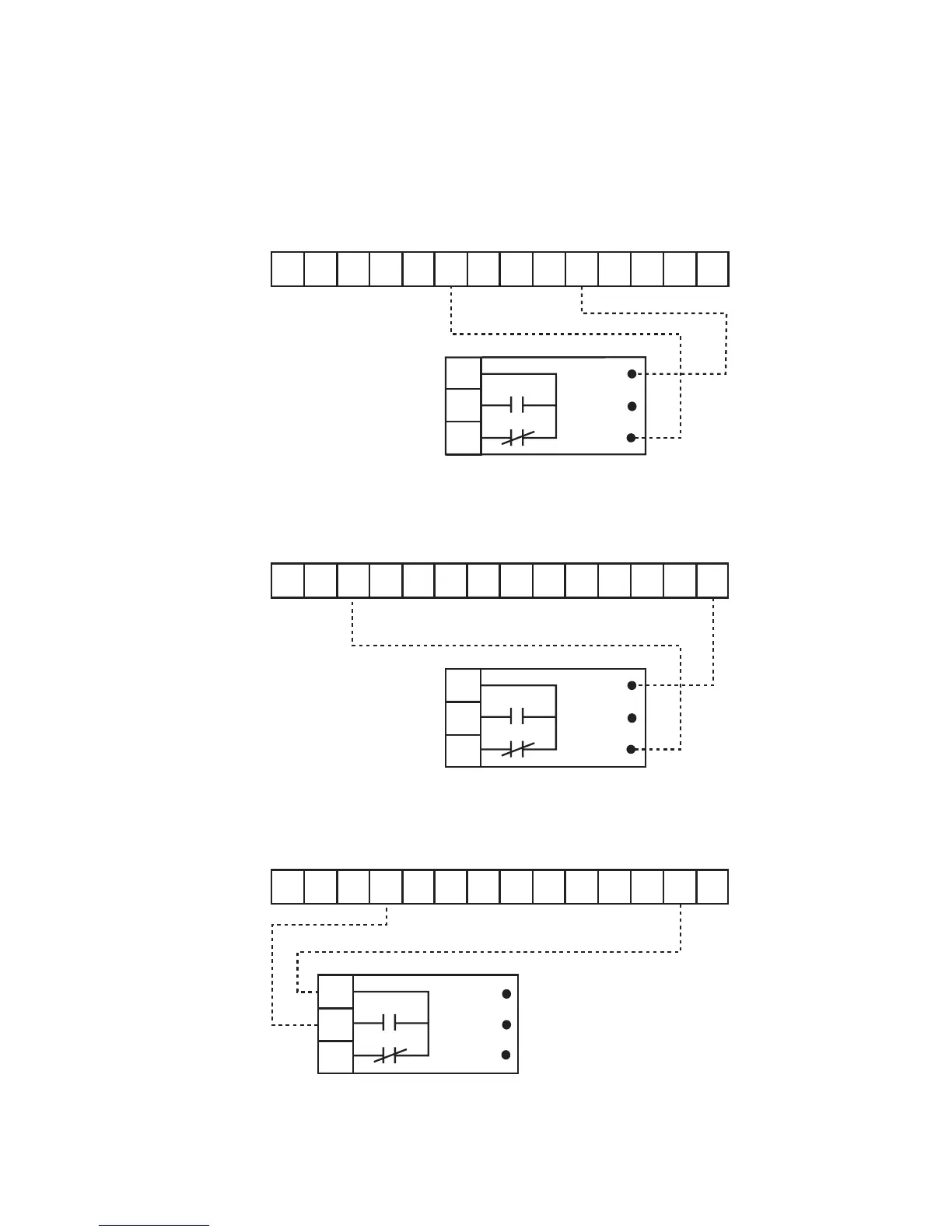
Operation: In this example the auxiliary relay contacts can be used
to indicate a fault condition. With the auxiliary relay connected as
shown, the normally open contacts will close during a fault condition.
Operation: In this example the auxiliary relay contacts can be used
to signal WSHP fan operation to another device. In this example when
the thermostat energizes the “G” terminal the auxiliary relay normally
open contacts will close.
Operation: In this example the auxiliary relay is used to interface other
control devices to the Mark IV/AC board. Using the Orange (-) and
White (+) wires, and 24vac or 24vdc, another device could be used to
start and stop the WSHP heating sequence.
can be used to provide fault signals, unit operation signals,
or to provide a means for remote equipment to control the
Mark IV/AC board. The orange, yellow, and white connec-
tions are short flying leads pre-attached to the board. The
diagrams shown are some connection examples.
IM 439 / Page 21
WSHP Mark IV/AC Board Low Voltage Terminal Strip
OW2GW1Y1 F E LUAPVRC
1
2
3
Auxiliary Relay
Orange
Yellow
White
WSHP Mark IV/AC Board Low Voltage Terminal Strip
OW2GW1Y1 F E L U A P V R C
1
2
3
Auxiliary Relay
Orange
Yellow
White
WSHP Mark IV/AC Board Low Voltage Terminal Strip
OW2GW1Y1 F E L U A P V R C
1
2
3
Auxiliary Relay
Orange
Yellow
White