18
M5MSY-2010 Application Information
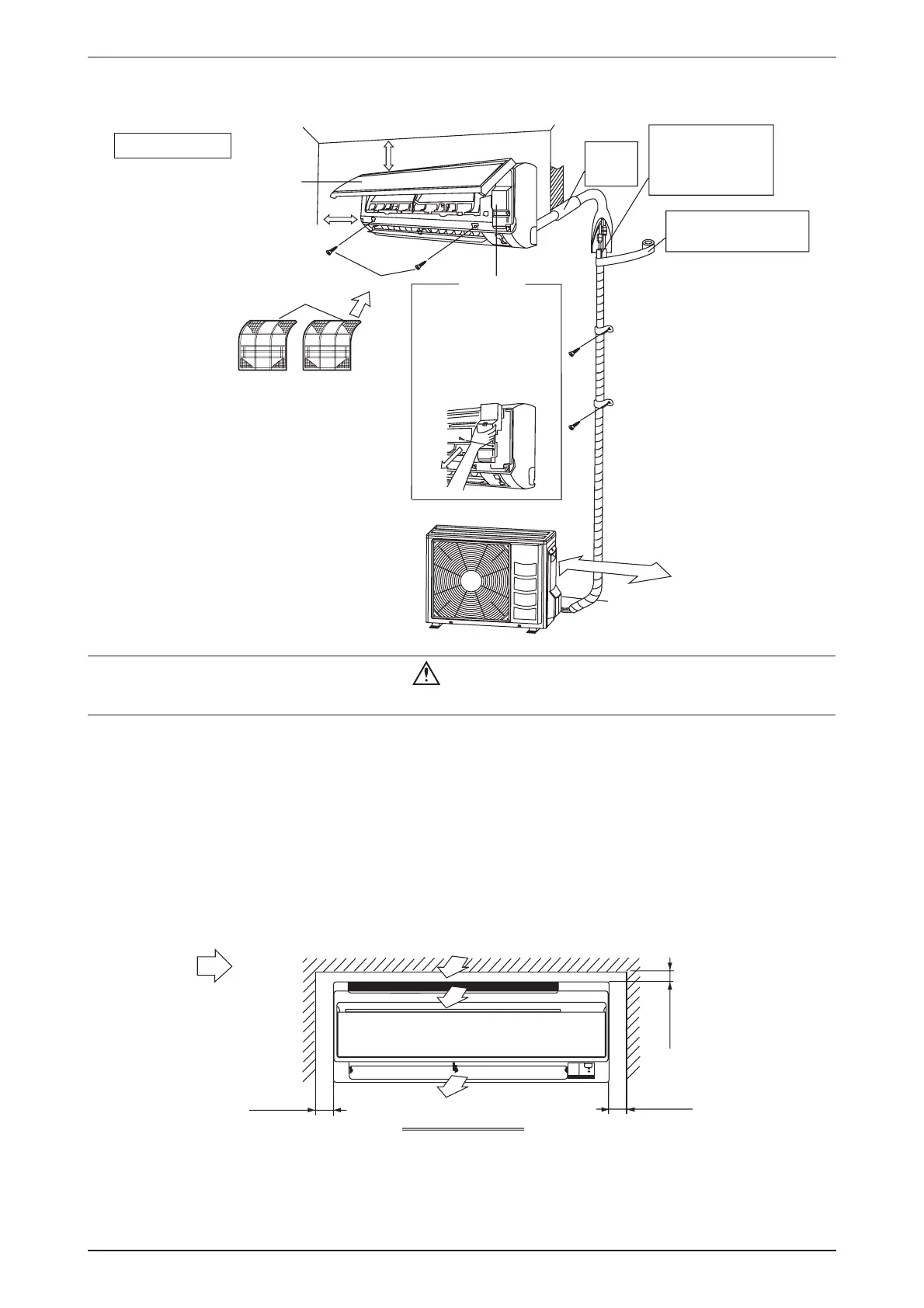
Installation Diagram
Air filter
M4 x 12L
Front panel
30mm or more from ceiling
50mm or more from walls
(on both sides)
Caulk pipe
hole gap
with putty.
Cut thermal insulation
pipe to an appropriate
length and wrap it with
tape, making sure that no
gap is left in the insulation
pipe’s cut line.
Wrap the insulation pipe with
the finishing tape from bottom
to top.
Service lid
••
••
• Opening service lid
Service lid is opening/closing
type.
••
••
• Opening method
1) Remove the service lid
screws.
2) Pull out the service lid
diagonally down in the
direction of the arrow.
3) Pull down.
l
l
a
w
mo
r
f
mm
0
5
2
Caution
Before installing the unit, ensure that the power supply matches the power requirement of the air conditioner.•
Service Space
Install the indoor unit at a location with the following requirements
Location is suitable for wiring, piping and drainage.
No obstruction of air fl ow into and out of unit where cooler air can be evenly distributed.
Ensure that air discharge is not short circuited with air intake.
Ensure that wall is suffi ciently strong, rigid, fl at, perpendicular and vibration free.
Where air fi lter cassette can be slided in or out easily.
Where there is no danger of fl ammable gases.
Where there is no direct sunlight on unit.
min. 50
(Space for
maintenance)
Air flow
(Indoor)
min. 50
(Space for
maintenance)
03.n
im
rofecapS(
)ecn
am
rofrep
Required space
•
•
•
•
•
•
•
Wall Mounted
 Loading...