1-8
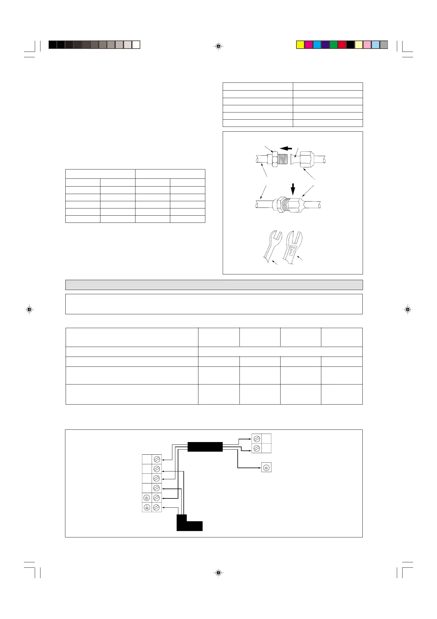
Ø TUBE A (mm)
INCH mm Imperial Rigid
1/4" 6.35 1.3 0.7
3/8" 9.52 1.6 1.0
1/2" 12.70 1.9 1.3
5/8" 15.88 2.2 1.7
3/4" 19.05 2.5 2.0
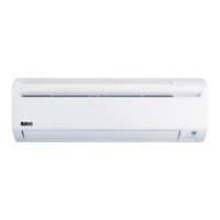
SPANAR
TORQUE WRENCH
INDOOR PIPING
FLARE NUT
FLARED TUBE
FLARE JOINT
PIPE SIZE (mm/in) TORQUE (Nm)
6.35 (1/4) 18
9.53 (3/8) 42
12.7 (1/2) 55
15.88 (5/8) 65
19.05 (3/4) 78
PIPING CONNECTION TO THE UNITS
Align the center of the piping and sufficiently tighten the
flare nut with fingers.
Finally, tighten the flare nut with torque wrench
until the wrench clicks.
When tightening the flare nut with the torque wrench,
ensure that the direction for tightening follows the arrow on
the wrench.
The refrigerant pipe connection are insulated by polyure-
thane (ARMAFLEX type or similar).
! Caution
ELECTRICAL CONNECTION
(Cooling only units for series 10C~25C with wire remote control & PCB)
IMPORTANT: These values are for information only, they should be checked and selected to comply with the local and/or
national codes and regulations. They are also subjected to the type of installation and size of
conductors.
INDOOR UNIT CC 10C CC 15C CC 20C CC 25C
OUTDOOR UNIT SL 10B SL 15B SL 20B SL 25B
Voltage range
220V – 240V /1Ph /50Hz + !
Recommended fuse A 610 16 20
Power Supply Cable size mm
2
1.5 1.5 2.5 2.5
Number of conductors 33 3 3
Interconnection Cable size mm
2
1.5 1.5 2.5 2.5
Number of conductors 33 3 3
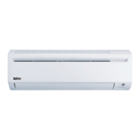
Ensure the color of wires of the outdoor unit and the terminal markings are same to
the indoors respectively.
The electrical power must be provided with protection
devices (circuit breaker or fuse) with double pole
separation system (phase + neutral) with minimum
contact gap of 3mm.
!
TERMINAL STRIP
INDOOR UNIT
INTERCONNECTION
CABLE
TERMINAL STRIP
OUTDOOR UNIT
Cooling only units for series 10C~25C with wire remote control & PCB
COMP
L
N
N
COMP
TH
CCC-0700 (01~16) ENG* 2/1/01, 10:42 AM8