1-16
The unit is equipped with a controller main board, and a wired remote controller is connected to the controller main board.
All the setting in the unit is preset by the manufacturer. It is not recommended to change the setting unless necessary.
a) Remote Controller Location
The remote controller is located on a metal bracket behind the service panel. It is packed together with installation manual.
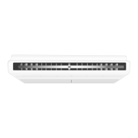
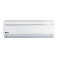
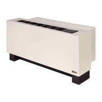
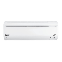
5RT90BR 5RT120/150/180BR
b) LED Display (Controller Main Board)
The LED will blink when power up the unit.
c) LCD Display (Remote Controller)
During normal operations, the LCD displays compressor on/off status, mode, set temperature and so on. Refer to
Operating Manual for the details of operation guide. The LCD will display the main screen upon power-up. When
malfunctioning occur, a pop-up message will appear on the LCD with backlight blinking and ʻbeepʼ sound.
d) Optional Confi gurations
The controller main board can be used as the interface for thermostat control and BMS system.
(i) Thermostat control (TB_THM-I)
• To use this control, set Dip Switch Setting: SW1-ON (default is OFF).
• Follow the method below for thermostat control inputs:
CONTROL OPERATION GUIDE
Remove
service
panel
Note:
• When the controller main board is confi gured as thermostat control, the remote controller is used for monitoring
purpose only.
• Unit needs to be restarted (power off and on) whenever dip switch setting is changed.
(ii) BMS control (TB_BMS-I)
• To use this control, set Dip Switch Setting: SW3 - ON (default is OFF) and panel parameter G8 to ʻ1ʼ.
• For TB_BMS-I, there are 3 control inputs:
unit on/off; operating mode (cool-0/heat-1); and set point (4~20mA).
• Refer below table for installation recommendations:
CONTROL
BOX
CONTROL
BOX
G Y1 Y2 W1 W2 Mode Operation
0 0 0 0 0 - Unit off
1 0 0 0 0 Cool Indoor fan on
X 1 0 X X Cool 1 stage compressor
X 1 1 X X Cool 2 stage compressor
X 0 X 1 0 Heatpump/Heater 1 stage compressor
X 0 X 1 1 Heatpump/Heater 2 stage compressor
Remark: X = Donʼt care.
• Refer table below for installation recommendations:
Input Rated voltage Rated current Wire size
G
24V AC 5mA AWG22~18
Y1
Y2
W1
W2
ON
OFF
TB_THM-I
Note:
• When the controller main board is confi gured as BMS control, the remote controller is used for monitoring
purpose only.
• Unit needs to be restarted (power off and on) whenever dip switch setting is changed.
1 2 3 4 5 6 7 8
ON
OFF
TB_BMS-I
Input TB_BMS-I Rated voltage Rated current Wire size
On/Off 24V AC 5mA
AWG22~18Operating mode 24V AC 5mA
Cool/Heat set point - 4~20mA
IM 1 5RTBR-1209(0)-EN.indd 16IM 1 5RTBR-1209(0)-EN.indd 16 1/14/10 11:37:41 AM1/14/10 11:37:41 AM
 Loading...