English
1-15
10 30
15
-15
-10
20
20
18
10
0
-20
27
52
50
43
40
20
10
30
0
-10
14
10 20
19
23 30
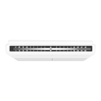
Arrangement of terminal blocks and components for controller are shown as below:
a) Control Module 5RT90BR
b) Control Module 5RT120/150/180BR
(Bottom Layer) (Top Layer)
OPERATING RANGE
Ensure the operating temperature is within the allowable range, as stated in diagram below:
Cooling
Heating
Outdoor DB temperature (°C)
Indoor WB temperature (°C)
Outdoor WB temperature (°C)
Indoor DB temperature (°C)
No. Item Description
1
Controller Main Board
2
EXV Controller Board
3
Capacitor
4
Contactor
5
Phase Protector
6
Relay
7
Terminal Block
8
Fuse
9
Transformer
1
9
5
6
8
7
4
7
3
2
1
9
5
6
8
7
4
7
3
2
4
7
The use of the air conditioner outside the
range of working temperature and humid-
ity can result in serious failure.
! CAUTION
IM 1 5RTBR-1209(0)-EN.indd 15IM 1 5RTBR-1209(0)-EN.indd 15 1/14/10 11:37:34 AM1/14/10 11:37:34 AM
 Loading...