28 IM708
Unit Options
Duct High Limit
A duct high limit (DHL) pressure control is provided as stan-
dard with all units having variable air volume control. The
duct high limit is intended to protect the ductwork, etc. from
over pressurization caused by tripped fire dampers or a con-
trol failure. When the duct pressure exceeds the setting of the
control, the unit is de-energized via the MicroTech II con-
troller and an alarm condition indicated. After the reason for
trip has been identified and corrected, the control can be
reset via the MicroTech II keypad/display interface.
The duct high limit is factory installed including sensing tub-
ing, and preset for a 3.0" wc trip point. The control can be
readjusted in the field to match the specific ductwork of a
project. The switch has a field adjustable set point range of
0.17 to 5.0 inches of H2O. Turn adjustment screw clockwise
to decrease differential pressure setting. Turn adjustment
screw counterclockwise to increase differential pressure set-
ting. DHL is located in the fan section on the motor side.
Phase Fail/Under Voltage Protection
The monitor is a microprocessor controlled device which
provides protection against three-phase electrical motor loss
due to low voltage, phase loss, voltage unbalance and phase
reversal. The microprocessor constantly monitors the three-
phase line voltages and detects these harmful power line
conditions. Whenever any of these conditions occur, the
SWP controls are deactivated and remain deactivated until
power line conditions return to an acceptable level. Trip and
reset delays have been provided to prevent nuisance tripping
due to rapid power fluctuations. The trip and reset delays are
field adjustable. The monitor also provides a variable line
voltage adjustment.
Duct Static Pressure Sensor
All units provided with variable air volume control include a
factory mounted static pressure sensor (SPS1). The unit can
also have an optional second static pressure sensor, SPS2.
The sensor is factory wired and requires field installation of
1/4" I.D. sensor tubing to the selected duct location.
Note: Be sure that tubing complies with local code
requirements. Flame retardant plastic or metal tub-
ing may be required. Carefully select the ductwork
sensing point for the pressure sensor. Improper
location of the sensing point will result in unsatis-
factory operation of the entire variable air volume
system. The following guidelines should be adhered
to:
1. Sense near the end of long duct runs to ensure that all
terminal box take-offs along the run will have adequate
static pressure to operate.
2. The end of the sensing tube must be perpendicular to the
airflow in order to sense only static pressure.
3. The sensing tube should be located in a nonturbulent
flow area of the duct. Keep several duct widths away
from take-off points, bends or neck downs.
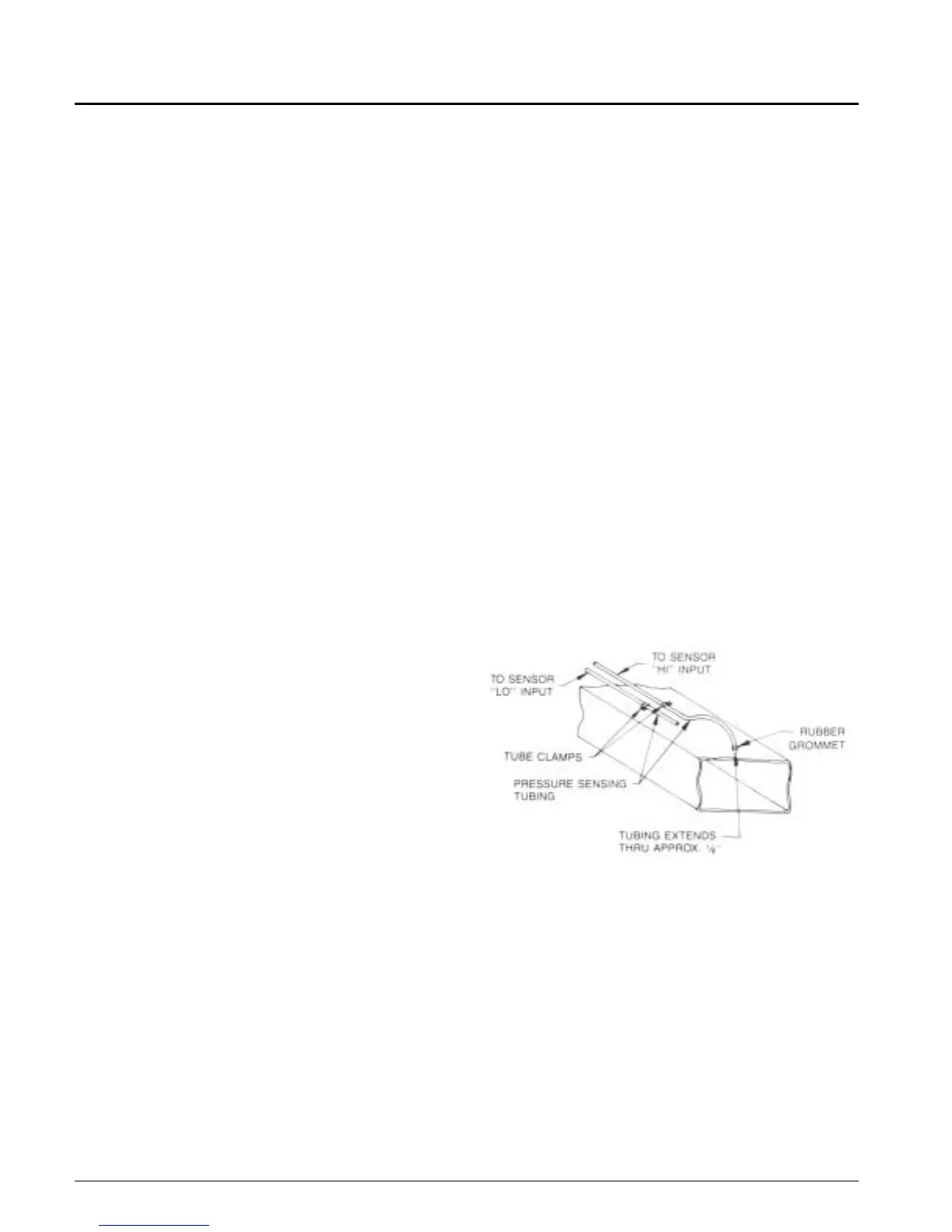
Mounting instructions (See Figure 28)
1. Drill hole in duct at remote sensing point and install a
rubber grommet. Insert sensing tube 1/8" into the duct
and securely clamp tubing to the duct, being sure not to
stress or kink the tubing. The end of the sensing tube
must be smooth and cut straight across. An angle cut
will affect operation.
2. Clamp a second tube to the outside of the duct at the
location of the sensing point.
3. Run both tubes along the ductwork and back to the unit.
The tubing may be routed to the pressure sensor (SPS1)
by drilling two holes through the unit upright post. A
grommet must be used at each hole to protect the tubing
and seal the cabinet.
Note: To avoid confusion between "high" and "low" tubing,
it is recommended that two different tubing colors be
used and that this information be recorded, along with
the sensing point location, on the master building blue-
prints.
4. Connect tubing to the high and low ports on the sensor.
Figure 28
Building Static Pressure Sensor
If a unit has direct building static pressure control capability,
static pressure taps must be field installed and connected to
pressure sensor SPS1 in the unit. This sensor is located on
the control panel.
The two static pressure sensing taps must be carefully
located and installed. Improper location or installation of the
sensing taps will cause unsatisfactory operation. Following
are pressure tap location and installation recommendations
for both building envelope and lab, or "space within a
space," pressure control applications. The installation must
comply with local code requirements.
 Loading...