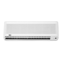
Model 5CKWS20AR 5CKWS25AR 5CKWS30AR 5CKWS40AR 5CKWS50AR
Coupling Unit 5WSS16AR 5WSS20AR 5WSS25AR 5WSS30AR 5WSS40AR 5WSS50AR
Nominal Cooling Capacity Btu/hr 16000 20000 25000 30000 38500 51500
kW 4.68 5.86 7.32 8.78 11.27 15.08
Nominal Heating Capacity Btu/hr 16500 20500 25500 31000 41500 54500
kW 4.83 6.03 7.47 9.08 12.15 15.96
Unit Nett Weight kg 31 + 4 32 + 4 35 + 4 38 + 4 40 + 4
Fan Motor 6 Poles x 35W 6 Poles x 50W 6 Poles x 65W 6 Poles x 85W 6 Poles x 120W
Fan Blower
Air flow rate (high speed) m
3
/min 20.9 22.1 24.9 28.0 29.5
Refrigerant Circuit
Liquid valve connection inches 1/4 1/4 3/8 3/8 3/8
Gas valve connection inches 1/2 5/8 5/8 5/8 5/8
Drain Pipe Connection inches 3/4 3/4 3/4 3/4 3/4
Air Filter WASHABLE SARANET FILTER
Ø Tube, D A (mm)
Inch mm Imperial Rigid
1/4" 6.35 1.3 0.7
3/8" 9.52 1.6 1.0
1/2" 12.70 1.9 1.3
5/8" 15.88 2.2 1.7
3/4" 19.05 2.5 2.0
REFRIGERANT PIPING WORK
Refrigerant piping is important in particular. Refrigerant cycle of the split air conditioner is realized by the perfect piping work.
1. Piping Length And Elevation
• If the piping is too long, both the capacity and reliability of unit will drop.
• As the number of bends increase, resistance to flow of refrigerant system increases, thus lowering cooling capacity and as a
result the compressor may become defective.
• Always choose the shortest path and follow the recommendation as tabulated below.
Model 5CKWS20AR 5CKWS25AR 5CKWS30/40/50AR
Maximum Length (m) 15 15 35
Maximum Elevation (m) 8810
Maximum No. of Bends 10 10 10
Liquid Pipe Size 1/4” 1/4” 3/8”
Gas Pipe Size 1/2” 5/8” 5/8”
Copper tube
Swaging block
Pipe Size mm / (in) Torque Nm / (ft - lb)
6.35 (1/4) 18 (13.3)
9.53 (3/8) 42 (31.0)
12.7 (1/2) 55 (40.6)
15.88 (5/8) 65 (48.0)
19.05 (3/4) 78 (57.6)
2. Piping Connection
• Do not use contaminated or damaged copper tubing. If any piping, evaporator
or condenser had been exposed or had been opened for 15 seconds or more,
then vacuum and purge with field supplied refrigerant. Generally, do not re-
move plastic, rubber plugs and brass nuts from the valves, fittings, tubing and
coils until it is ready to connect suction or liquid line into valves or fittings.
• If any brazing work is required, ensure that nitrogen gas is passed through coil
and joints while the brazing work is being done. This will eliminate soot forma-
tion on the inside wall of copper tubings.
• Cut the pipe stages by stages, advancing the blade of pipe cutter slowly. Extra
force and a deep cut will cause more distortion of pipe and therefore extra burr.
• Remove burrs from cut edges of pipes with a remover. This will avoid uneven-
ness on the flare face which will cause gas leak.
• Flare the pipe with extra length above the flaring tool as shown in the table
beside.
• The flared edge must be even and not cracked or scratched.
• Align the center of the piping and sufficiently tighten the flare nut with fingers.
Finally, tighten the flare nut with torque wrench until the wrench clicks.
• Be sure to execute heat insulation. (Polyurethane form with thickness more
than 15mm)
• Except the water source heat pump unit which is pre-charge with refrigerant,
the fan coil unit and the refrigerant connection pipes must be purged because
the air that contain moisture remaining in the refrigerant cycle may cause mal-
function to the compressor.
PHYSICAL DATA
R410A – Heat Pump
D
A
 Loading...