47
31-SAFETY DEVICES AND ALARMS
Technical Dept. - All rights reserved - Reproduction prohibited
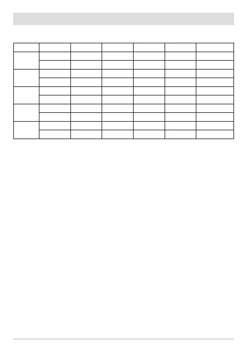
NEGATIVE PRESSURE INSIDE THE HOPPER WITH FACTORY-SET PARAMETERS AND A DRAUGHT OF 5 Pa (MINIMUM
RECOMMENDED)
POWER P1 P2 P3 P4 P5 VALUES
6 kW
13.7/14.2 Pa 15.1/15.6 Pa 17.1/17.5 Pa 19.1/19.5 Pa 22.0/22.2 Pa Draught
95°C 110°C 125°C 141°C 165°C Smoke temperature
8 kW
13.8/14.3 Pa 15.6/16.1 Pa 17.8/18.0 Pa 21.7/22.2 Pa 26.1/26.6 Pa Draught
104°C 119°C 145°C 148°C 184°C Smoke temperature
10 kW
15.9/16.3 Pa 20.4/20.9 Pa 25.8/26.3 Pa 31.8/32.3 Pa 36.5/37.0 Pa Draught
108°C °C 150°C °C 230°C Smoke temperature
12 kW
16.5/17.3 Pa 20.4/20.9 Pa 25.8/26.3 Pa 31.8/32.3 Pa 36.5/37.1 Pa Draught
118°C 127°C 155°C 172°C 195°C Smoke temperature
14 kW
17.6/18.0 Pa 19.8/20.4 Pa 23.1/23.7 Pa 28.9/29.6 Pa 37.8/38.2 Pa Draught
118°C 131°C 161°C 187°C 210°C Smoke temperature
PLEASE NOTE The indicated negative pressure readings may dier by ±1Pa based on ue gas temperature. Likewise, ue gas temperature
may dier by ±10°C based on fuel quality or appliance cleanliness.
Changing the smoke fan revolutions
In order to further improve combustion in critical conditions, you can change the percentage of the parameters for the minimum amount
of incoming combustion air. These changes can be performed upwards in the event of serious diculties in evacuating smoke and/or air
intake or downwards in the event of excessive draught of the ue.
Refer to AIR RECIPE modication instructions.
AVAILABLE VALUES
-2 -10%
-1 -5%
0 0% (default value)
+1 + 5%
+2 +10%