Do you have a question about the Mean Well WDR Series and is the answer not in the manual?
Maintain 5mm side, 40mm top, and 20mm bottom clearances to prevent overheating.
Mount vertically with input terminals down and output terminals up. Other orientations are disallowed.
Use copper wire only, with specific AWG and cross-section recommendations based on current.
Use wires rated for at least 80°C, such as UL1007.
Recommended wire strapping length is 7mm (0.275").
Use a 3mm slotted type screwdriver for terminal connections.
Details recommended torque settings for terminals, referring to a table not shown here.
Suggested fuse types and maximum unit counts per circuit breaker at 400V are provided.
Unit can connect to 2 phases of a 3-phase Wye system; AC/L2 input requires protection.
Step-by-step guide for fastening the unit onto a TS35 DIN rail.
All failures must be examined by a qualified technician. Do not remove the power supply case.
Connecting primary and secondary sides together is not allowed.
Do not touch the unit during operation or shortly after disconnection.
Protect openings from foreign objects and dripping liquids.
Maximum operating temperature is 50°C; avoid high ambient temperatures or fire sources.
Specific compatibility note for WDR-480 with certain surge protective devices.
Do not place units in areas with high moisture or near water.
Avoid locations with high ambient temperature or near fire sources.
The FG terminal must be connected to PE (Protective Earth).
Output current and wattage must not exceed specified rated values.
Disconnect system from supply voltage before any installation or maintenance.
For continued protection against fire, replace fuses with the same type and rating.
| Output Voltage | 12V, 24V, 48V |
|---|---|
| Operating Temperature | -30°C to +70°C |
| Efficiency | Up to 94% |
| Protection | Over voltage, Over current, Short circuit, Over temperature |
| Cooling | Free air convection |
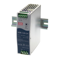
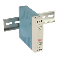
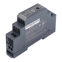
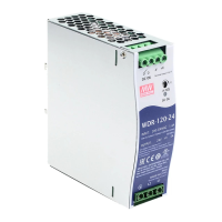
| Mounting | DIN Rail TS-35 / 7.5 or 15 |
| DC Adjustment Range | ±10% |
| EMC Standards | EN 55032, EN 61000-3-2, EN 61000-4 |