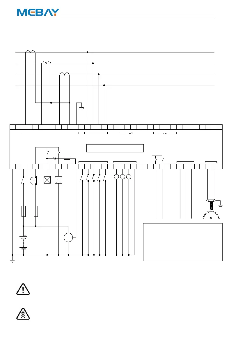
GEN CURRENT
GEN VOLTS
BATTERY
FUSE 10 A
FUSE 20 A
FUEL
CRANK
BATTERY NEGATIVE MUST BE GROUNDED
SWITCH
AUX. OUTPUT 3
AUX. OUTPUT 4
ALT
(AC0-6A)
SENDER COMMON
AUX. SENSOR 1_OIL PRESSURE
AUX. SENSOR 2_COOLANT TEMP
AUX. SENSOR 3
AUX. OUTPUT 1
AUX. OUTPUT 2
AUX. INPUT 1_HIGH COOLANT TEMP ALARM
AUX. INPUT 2_LOW OIL PRESSURE ALARM
AUX. INPUT 3_REMOTE START
AUX. INPUT 4_LOW FUEL LEVEL WARNING
AUX. INPUT 5_LOW COOLANT LEVEL ALARM
EMERGENCY
STOP
FROM GENERATOR
CTs MUST BE 5 AMP SECONDARY
TO LOAD SWITCHING
DEVICE
14
13 19
5
4
3
2
1
30
L3
2928
L2L1
34
L2
31
N
3332
9
L1
L3
COM
23 6
2625
24 27
7
WL
10
35
8
15
12
18
11
16
17
20
21 22
P1 P2
S1S2
P1 P2
S1S2
P1 P2
S1S2
36
MODEL: DC40D MK3
+VE
RS485
RS485_SCR
RS485_B
RS485_A
SCR
B A
+
-
MPU
DC 8-36V
+
-
MAX 5A
MAX 5A
1.No. 23 common sensor lines must be
securely attached to the vicinity of the sensor
body.
2.To ensure reliable operation of the module
and the measuring accuracy, power lines as
much as possible and do not share power
cable crude and other devices.
REMARK:
INPUTS INPUTS
L1
L2
L3
N
(AC30-300V)
 Loading...