Do you have a question about the Mebay DC8-D MK Series and is the answer not in the manual?
Overview of the genset controller's purpose and capabilities.
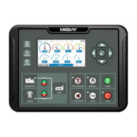
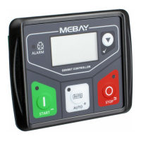
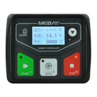
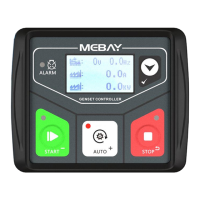
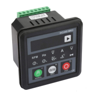
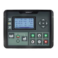
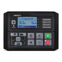
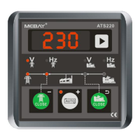
Details about the four models and key features of the DC8xD MK3 series controllers.
Lists various parameters displayed by the controller, including engine, generator, and mains status.
Lists technical specifications and options for the controller, including voltage, consumption, dimensions, and protection levels.
Provides overall dimensions and a visual representation of the controller's physical size.
Details the function, description, and cable cross-sectional area for each terminal on the controller.
Illustrates the typical wiring diagram for the DC80D MK3 controller in a 3-phase, 4-wire configuration.
Illustrates the typical wiring diagram for the DC82D MK3 controller in a 3-phase, 4-wire configuration.
Provides guidance on how to physically install the controller, including mounting and connections.
Details requirements for connecting the battery voltage supply to the controller.
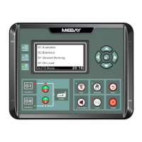
Describes the physical panel layout and the display screen for both DC80D MK3 and DC82D MK3 models.
Explains the function of each key on the controller's panel for operation and navigation.
Describes the procedure for starting the genset manually and the subsequent parking process.
Explains the process for automatic genset startup triggered by external signals or mains failure.
Introduces warnings and shutdown alarms, explaining their purpose and general behavior.
Describes the warning generated when the low fuel level sensor indicates a critical fuel level.
Introduces shutdown alarms, explaining their immediate effect and the need for troubleshooting.
Details the alarm condition and action for exceeding the maximum engine speed.
Describes the alarm condition and action for falling below the minimum engine speed.
Explains the alarm triggered by low engine oil pressure detected by the sensor.
Guides users through the process of entering the edition page and setting parameters.
Allows selection of the display language for the controller interface.
Sets the number of poles for the generator, affecting RPM calculations.
Selects the AC system configuration (phase and wire count) for the generator.
Sets the Current Transformer (CT) rate for accurate current measurement.
Sets the rated frequency of the generator for meter range and alarm calculation.
Sets the rated phase voltage for meter range and alarm calculation.
Sets the rated phase current for meter range and alarm calculation.
Sets the total generator power for meter range and loading rate calculation.
Sets the rated battery voltage for meter range and alarm calculation.
Sets the rated RPM for meter range and alarm calculation.
Sets the number of flywheel teeth for RPM calculation, or disables RPM if set to 0.
Selects the type of oil pressure sensor or defines a user-defined option.
Selects the type of coolant temperature sensor or defines a user-defined option.
Selects the type of fuel level sensor or defines a user-defined option.
Defines the controller's action (warning, alarm, trip stop) for over current events.
Defines the controller's action for over power events.
Defines the controller's action when the RPM signal is lost.
Defines the controller's action for a disconnected oil pressure sensor.
Defines the controller's action for a disconnected temperature sensor.
Selects the unit of measurement for pressure and temperature displays.
Sets the number of crank attempts allowed in manual mode.
Sets the number of crank attempts allowed in auto mode.
Configures the conditions under which crank disconnect is considered successful.
Sets the condition for crank success based on RPM relative to a preset value.
Sets the condition for crank success based on frequency relative to a preset value.
Sets the condition for crank success based on oil pressure relative to a preset value.
Sets the timing for the fuel pump output when fuel level is low.
Sets the timing for the fuel pump output when fuel level is sufficient.
Sets the maintenance interval in hours.
Sets the date for the next maintenance.
Allows changing the user password for parameter access.
Enables or disables ATS (Automatic Transfer Switch) functionality in manual mode.
Configures various delay times for different operational sequences and alarms.
Sets the delay time after mains failure or remote signal before genset startup.
Sets the time for preheating the engine before the starter engages.
Sets the duration the starter is engaged during cranking.
Sets the waiting time between crank attempts if crank failure occurs.
Sets the delay for crank success based on oil pressure reaching a preset value.
Sets a delay period where certain alarms are ignored except for critical ones.
Sets the idle running time after successful cranking.
Sets the maximum time for speed increase before system exits.
Sets the time needed for the generator to reach rated load.
Sets the delay before transferring back to mains power.
Sets the delay for transferring to genset from mains under certain conditions.
Sets the engine cooling down time after unloading before shutdown.
Sets the idle running time after stopping the genset.
Sets the time the stop solenoid remains energized.
Sets the time limit to detect stop failure.
Sets the delay for emergency and over frequency alarms.
Sets the delay for normal alarms, excluding emergency stop and over frequency.
Sets the delay for over/under voltage alarms.
Sets the delay for over phase current alarms, can be inverse time.
Sets the delay for over total power alarms, can be inverse time.
Defines inverse time calculation for over current alarms.
Defines inverse time calculation for over power alarms.
Sets pulse width for mains and gens loading/unloading.
Sets the delay for fuel valve relay output before cranking.
Configures alarm thresholds and actions for various engine parameters.
Sets the threshold and action for over speed alarms.
Sets the threshold and action for under speed alarms.
Sets the threshold and action for low oil pressure alarms.
Sets the threshold and action for high temperature alarms.
Sets the threshold and action for low fuel level warnings.
Sets the threshold and action for under battery voltage warnings.
Sets the threshold and action for over frequency alarms.
Sets the threshold and action for under frequency alarms.
Sets the threshold and action for over voltage warnings.
Sets the threshold and action for phase current over-load alarms.
Sets the threshold and action for under voltage alarms.
Sets the threshold and action for over total power warnings.
Configures the functions and behavior of the controller's outputs and inputs.
Configures the function of AUX. OUTPUT 1, including Preheat mode 1.
Configures the function of AUX. OUTPUT 2, including Public alarm output.
Configures the function of AUX. OUTPUT 3, including Audio alarm control.
Configures the function of AUX. OUTPUT 4, including Fuel pump and Crank output.
Configures the function of AUX. OUTPUT 5, including Genset running and Idle speed control.
Configures the function of AUX. INPUT 1, typically for remote start.
Configures the function of AUX. INPUT 2, typically for high temperature alarm.
Configures the function of AUX. INPUT 3, typically for low oil pressure alarm.
Configures the function of AUX. INPUT 4, typically for low fuel level warning.
Configures the function of AUX. INPUT 5, typically for low water level alarm.
Configures protection parameters related to mains power supply.
Selects the phase configuration for mains power input.
Sets the threshold for low mains voltage detection.
Sets the threshold for reverting from low mains voltage condition.
Sets the threshold for high mains voltage detection.
Sets the threshold for reverting from high mains voltage condition.
Sets the delay time for mains normal status recognition after an abnormal period.
Sets the delay time for recognizing mains abnormal status.
Configures settings related to the LCD display.
Sets the duration for the initial start screen display.
Adjusts the brightness level of the LCD screen.
Configures the LCD's automatic dimming or off behavior.
Sets the time for the page to revert back to the home page.
Configures the delay for the logo display when the unit is on standby.
Details settings related to USB and RS485 communication ports.
Sets the unique identification number for the controller on the network.
Sets the communication speed for the RS485 port.
Allows setting the current date, time, and day of the week.
Sets the current date and time for the controller's internal calendar.
Sets the current time of day for the controller.
Allows user-defined configuration of sensor curves for oil pressure and temperature.
Defines resistance curves for oil pressure sensors.
Defines voltage curves for oil pressure sensors.
Defines curves for water temperature sensors.
Defines curves for fuel level sensors.
Provides a guide to diagnosing and resolving common symptoms and faults.
Lists possible solutions for when the controller does not respond to power.
Lists possible solutions for unexpected genset shutdowns.
Lists possible solutions for the genset emergency stop function.
Lists possible solutions for low oil pressure alarms.
Lists possible solutions for high temperature alarms.
Lists possible solutions for shutdown alarms occurring during operation.
Lists possible solutions for failure to start the genset.
Lists possible solutions when the starter motor does not respond.
Lists possible solutions when the ATS does not switch despite unit operation.
Lists possible solutions for abnormal USB communication.
Lists possible solutions for abnormal RS485 communication.
| Frequency | 50/60Hz |
|---|---|
| Display | LCD |
| DC Power Supply | 10-35 VDC |
| Programmable Relay Output 1&2 | 5A @ 240 VAC/30 VDC |
| Storage Temp | -40~85°C |
| Communication Interface | RS485 |
| Storage Temperature | -40~85°C |