DC8xD MK3 GENSET CONTROLLER USER MANUAL
11
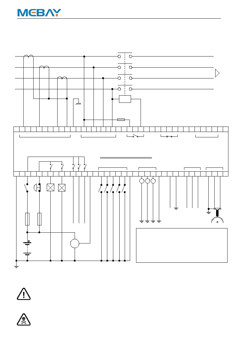
DC80D MK3 3-phase 4-wire Typical Wiring Diagram
Note: Please don’t move battery during running status or it may cause the
controller broken!
WARNING: When generator is on-load, C. T. secondary must not be open
circuit, Otherwise, the high voltage generated will pose a danger to personal safety.
GND
AUX. S2_COOLANT TEMP
AUX. S3_FUEL LEVEL
CTs MUST BE 5 AMP SECONDARY
FROM GENERATOR
TO LOAD SWITCHING
DEVICE
AUX. INPUT 5_LOW COOLANT LEVEL ALARM
AUX. INPUT 2_HIGH COOLANT TEMP ALARM
AUX. INPUT 4_LOW FUEL LEVEL WARNING
AUX. INPUT 3_LOW OIL PRESSURE ALARM
AUX. INPUT 1_REMOTE START
AUX. S1_OIL PRESSURE
11
109
45
44
5
43
21
46
37
T
3635
SR
41
CT2
38
N1
MODEL: DC80D MK3
BATTERY FUSE 10A
FUSE 20A
EMERGENCY
INPUTS
FUEL
CRANK
BATTERY NEGATIVE MUST BE GROUNDED
SWITCH
4039
CT1 CT3 COM
17
18
D+
42
12
6
13
14
47
ALT
P1
P2
S1
S2
P1 P2
S1S2
P1 P2
S1S2
R
S
T
N1
7 8
16
WL
AUX. OUTPUT 1
MAX 5A
MAX 16A
30 33
W
3231
V
U
34
N2
27
29 28
(MAX 5A)
G
(MAX 5A)
DC8-36V
+
-
+
-
1519
24
2523
B A SCR
RS485 MPU
43
48 49
+5V OUTPUT
(AC30-276V)(AC 0-5A)
GEN CURRENT
GEN VOLTS AUX. OUTPUT 5 AUX. OUTPUT 4
(AC30-276V)
MAIN VOLTS
GND
AUX. OUTPUT 2
AUX. OUTPUT 3
STOP
1.No. 47 common sensor lines must be securely
attached to the vicinity of the sensor body.
2.To ensure reliable operation of the module and the
measuring accuracy, power lines as much as
possible and do not share power cable crude and
other devices.
REMARK:
FUSE 2A
GND
INPUTS

 Loading...