Do you have a question about the Mebay DC30D and is the answer not in the manual?
Details professional installation, manual reading, safety standards, and overspeed protection.
Details on power supply connection, floating charger, and not disconnecting the battery.
Overview of the controller's purpose, interface options, and configuration methods.
Highlights key technical specifications and capabilities like LCD display, USB port, and module design.
Lists engine and generator parameters that the controller can display.
Details various protection features such as over speed, under speed, low oil pressure, and voltage alarms.
Lists operational parameters like voltage, power consumption, frequency input, and relay outputs.
Provides physical dimensions, panel cutout details, and a general wiring diagram overview.
Explains the function of each terminal connection for wiring the controller.
Guidance on how to install the controller, including panel cutout and battery voltage input requirements.
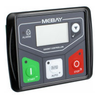
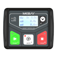
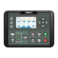
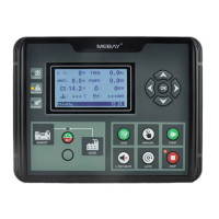
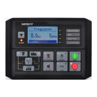
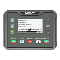
Identifies the components of the controller's panel, including LCD, alarm indicator, and buttons.
Explains the main functions and operations of each button on the controller panel.
Describes how to access and review stored alarm records on the controller.
Details manual start and stop procedures for the genset.
Important notes and considerations during the genset starting sequence.
Lists various warning conditions and their immediate effects on the genset.
Explains specific alarms related to sensor disconnections and maintenance expiration.
Details alarms for startup failures, overspeed, underspeed, and sensor issues.
Describes alarms related to generator voltage and current levels being outside normal ranges.
Covers alarms indicating the genset failed to stop correctly or system issues.
Outlines the steps and procedures for configuring the controller's parameters.
Configuration options for language, gens poles, and AC system wiring.
Configuration parameters for various time delays like start, stop, and crank times.
Parameters for configuring engine-related alarms like speed, pressure, and temperature.
Parameters for configuring generator alarms like frequency, voltage, and current.
Configuration options for programmable outputs and inputs.
Settings for the LCD display, including start screen time and saving mode.
Customization for sensor curves and automatic adjustment of flywheel teeth.
Provides common symptoms and their possible solutions for troubleshooting.
The DC30D Genset Controller is a specialized device designed for the automatic start, stop, monitoring, and fault checking of small diesel, gasoline, and gas generator sets. It also allows for parameter setting.
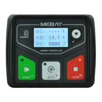
The controller features a point array LCD screen that can display various faults simultaneously, stopping the genset if it cannot operate smoothly. It offers Chinese/English interface options, with additional languages configurable by the user. All parameters can be set via the front panel buttons or through a programmable interface using a USB connection to a PC. This makes it widely applicable for various auto control systems in gensets.
The DC30D controller utilizes 32-bit micro-procession technology and features a 1.8-inch 128x64 LCD display with backlight. The PC front face panel is waterproof, oil-proof, and UV-proof, ensuring durability. A USB port allows parameter setting even without power. The controller collects and displays a variety of engine and generator parameters and records real-time faults. It has 5 relay outputs, 3 of which are configurable with over 10 selectable functions per channel. There is 1 switch value input, configurable for up to 20 functions. It includes 3 sensor simulation input connectors, supporting various unit types, and sensors can be self-defined via the front panel or PC software. The device offers various crank conditions (RPM, Frequency, Oil Pressure) and provides control protection for auto start/stop, load transfer, and comprehensive failure display and protection. It comes with a standard waterproof rubber gasket, achieving an IP54 rating. The modular design uses European connectors for easy installation, connection, repair, and replacement.
The controller displays:
The DC30D provides protection against:
The controller should be installed using four accessories and screws. The panel cutout dimensions are W78mm*H66mm. If installed directly in the genset shell or other fluctuating equipment, a rubber pad must be used. The DC30D is suitable for 98-18 VDC battery voltage. The battery negative must be reliably connected to the engine enclosure. The controller's power supply B+ and B- must be connected to the battery positive and negative, with wire size not less than 1.5mm². For floating chargers, connect the charger output directly to the battery positive and negative, then connect the battery positive and negative poles to the controller's positive and negative power supply. For AC current input, an external current transformer with a rated secondary current of 62.5mA must be connected to the controller's current input. During a withstanding voltage test, all controller terminal connections should be unplugged to prevent high voltage damage.
The controller can save three groups of alarm records, including detailed data such as alarm time, generator parameters, and engine parameters. These records can be checked in stop mode by pressing the STOP button for more than 3 seconds. The alarm records can be navigated using the AUTO+ and MANUAL buttons, and confirmed with the PAGE/CONFIRM button. The controller also features a maintenance countdown function, which can be set to trigger a warning or alarm when maintenance is due. The user password for parameter setting is "07623" by default, and a master password "97011" can revert all parameters to default settings.
The controller differentiates between warnings (non-serious failures that do not stop the genset but require attention) and shutdown alarms (serious failures that immediately lock the system and stop the genset). Shutdown alarms require troubleshooting and pressing the STOP button to clear before re-operation. Examples of warnings include Low Fuel Level Sensor Warning, External Instant Warning, Maintenance Expiration Warning, High Battery Voltage Warning, and Under Battery Voltage Warning. Shutdown alarms include Over Speed, Under Speed, Oil Pressure Sensor Opened, High Temperature Sensor Opened, Fuel Level Sensor Opened, Low Oil Pressure Sensor, High Temperature Sensor, High Temperature Switch, Low Fuel Level Switch, External Instant Alarm, Over Frequency, Under Frequency, Over Voltage, Under Voltage, Over Current, Maintenance Expiration Alarm, Low Water Level Switch, Emergency Stop, Stop Failure With Speed, Stop Failure With Frequency, and Stop Failure With Pressure.
Parameters can be set in stop mode by simultaneously pressing the STOP and PAGE/CONFIRM buttons. The "Set Parameters" menu is accessed by pressing the PAGE/CONFIRM button and entering the default password "07623". Parameters can be browsed using AUTO+ and MANUAL buttons, and values can be adjusted using AUTO+ (increase) and MANUAL (decrease) buttons. The STOP button cancels modifications, and the PAGE/CONFIRM button saves parameters and exits the edition page. The controller also supports automatic adjustment of flywheel teeth by starting the generator in manual mode and simultaneously pressing MANUAL and PAGE/CONFIRM for more than 0.5 seconds.
| Brand | Mebay |
|---|---|
| Model | DC30D |
| Category | Controller |
| Language | English |