11
4) Turn the trimmer screw, TRIM1 [25] until it shows on the display [10] the value zero.
5)
Replace the 4-20mA assembled board and fix the two screws (page 11).
(If it is present)
6) Replace the green panel and fix the 4 screws.
7) Close the transparent cover and tighten the 2 screws [18].
14. DISPLAY MESSAGES
PP1: MPS indicates that ALARM ∆P has been exceeded.
PPP: The maximum valve of ∆P in the MPS unit has been exceeded (2.50KPa).
P---: ∆P value is < 0KPa.
In this case check that filtered taps are correctly connected to the pressure ports of MPS as
described in paragraph 6.2.
Should the problem continue:
• Disconnect the tubes between filtered taps and pressure ports.
• Turn trimmer [25] to bring display back to 0 kPa.
• Connect the tubes between filtered taps and pressure ports.
SB: the REMOTE contact is activated [12].
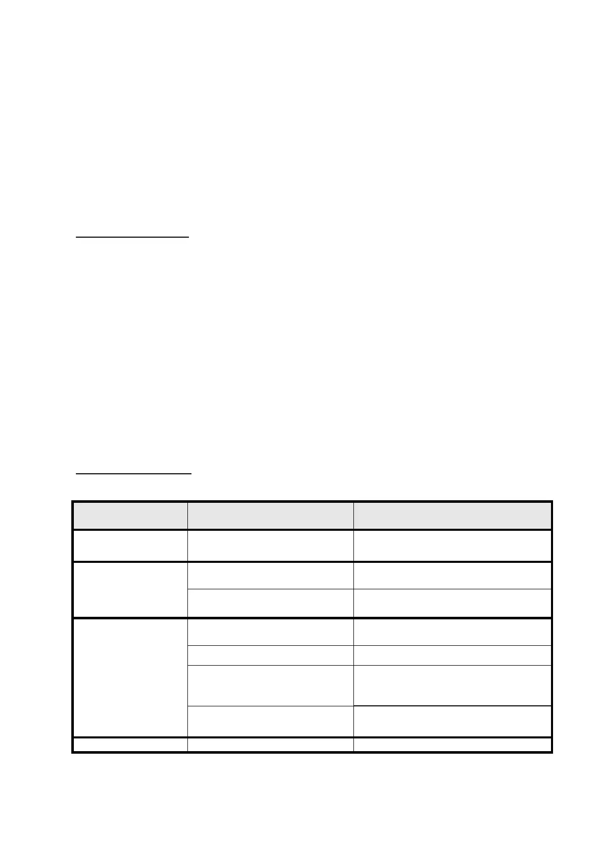
15. TROUBLESHOOTING
PROBLEM PROBABLE CAUSE SOLUTION
Display is blank and all
LED are off.
No power supply. Check the electrical terminals [15].
Wrong electrical connections
between MPS and coils.
Check connections [14].
Some valves are
ignored by MPS.
Coils are interrupted. Check coils continuity.
The secondary of the transformer
is interrupted.
Contact MECAIR
Power circuit is damaged. Contact MECAIR
Power supply to the valves are
different from voltages indicated
on the coils.
Contact MECAIR
Display shows the
pulsing sequence but
valves are not
functioning.
Wrong connections between MPS
and coils.
Check connections [14].
LED OK [6] is off. Microprocessor failure. Contact MECAIR
 Loading...