23
NNUAL PM INSTRUCTIONS
PREVENTATIVE MAINTENANCE KIT
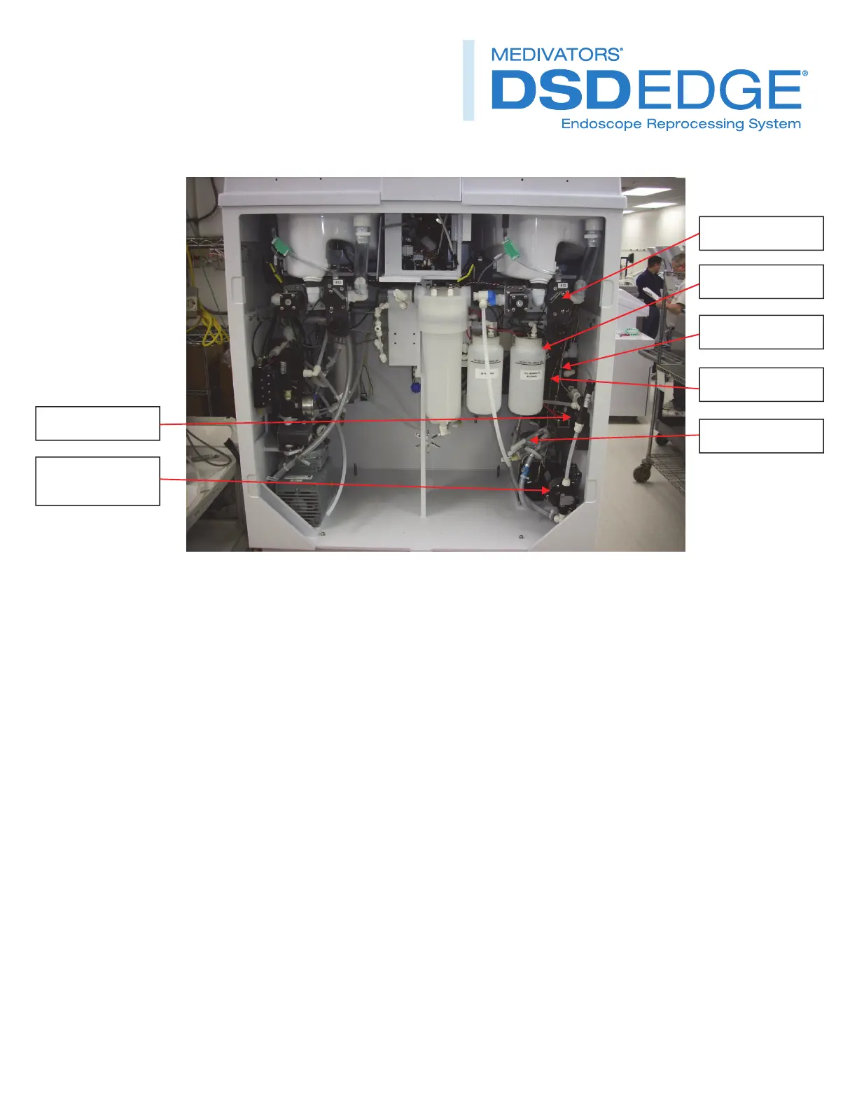
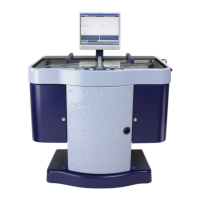
Figure 29
Electrical
Disconnect the B side FL1 flow sensor electrical connector. Refer to figure 29.
Disconnect the B side FL2 flow sensor electrical connector.
Disconnect the B side 6 station MAC valve manifold connector.
Disconnect the B side alcohol/detergent connector.
Disconnect the B side compressor.
Disconnect the B side disinfectant pump connector.
Disconnect the B side isolation valve connector.
Mechanical
Remove the three bolts that secure the B side main module to the unit. Two are located on the top of the pallet and
one near the right rear corner of the compressor.
Slide the B side module out of the unit.
FL1flowsensor
Drainvalves
MACvalve
Isolationvalve
Compressor
FL2flowsensor
Disinfection
pump