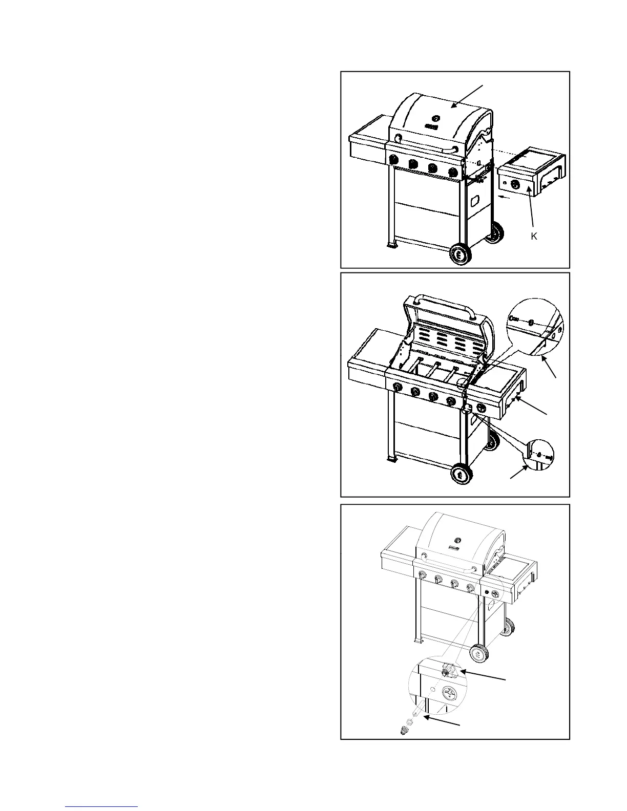
Fig. 13 A10. Side Burner Right Assembly
a) Loosen but do not remove two screws which are pre-
assembled on right side of Firebox (A). Align the holes
and secure the Side Burner Right (K) from inside
firebox by using 3pcs Truss Head Screws (H2) and
3pcs Flat Washers (H6) to attach the Side Burner Right
3xH2
3xH6
K
(K) to the Firebox (A). As shown in Fig.13 and
Fig.14.a1.
b) Tighten screws loosened in 10a. Ensure all screws are
tight.
Fig. 14
c) Using 1pc Truss Head Screw (H1) and 1pc Flat
Washer (H5) to attached the Side Burner Right (K) to
the right side of main control panel. As shown in
Fig.14.a2.
1xH1
1xH5
K
a1
11. Pulse Igniter Module and Battery Assembly
igniter. Insert Pulse Igniter Module (AB) through from
back of side burner control panel, secure lock washer
from front of side burner control panel. As shown in
Fig.15.
b) Install Battery (AC) into ignition box with positive
terminal (+) facing outward.
18
c) Replace the ignition battery cap after the Battery has
been installed. As shown in Fig.15.
AB
AC