Self test
Before commencing any measurements with
the TPT320 a self test should be made. Short
the probes tips together; the continuity LED will
illuminate and a continuous audible tone will be
heard. This procedure checks the batteries have
sufficient power to operate the voltage tester
correctly.
CAUTION: This test does not indicate the tester
is capable of indicating correct supply voltage;
a known live supply or a dedicated proving unit
should be utilised to check the voltage measuring
capability of the unit before and after testing.
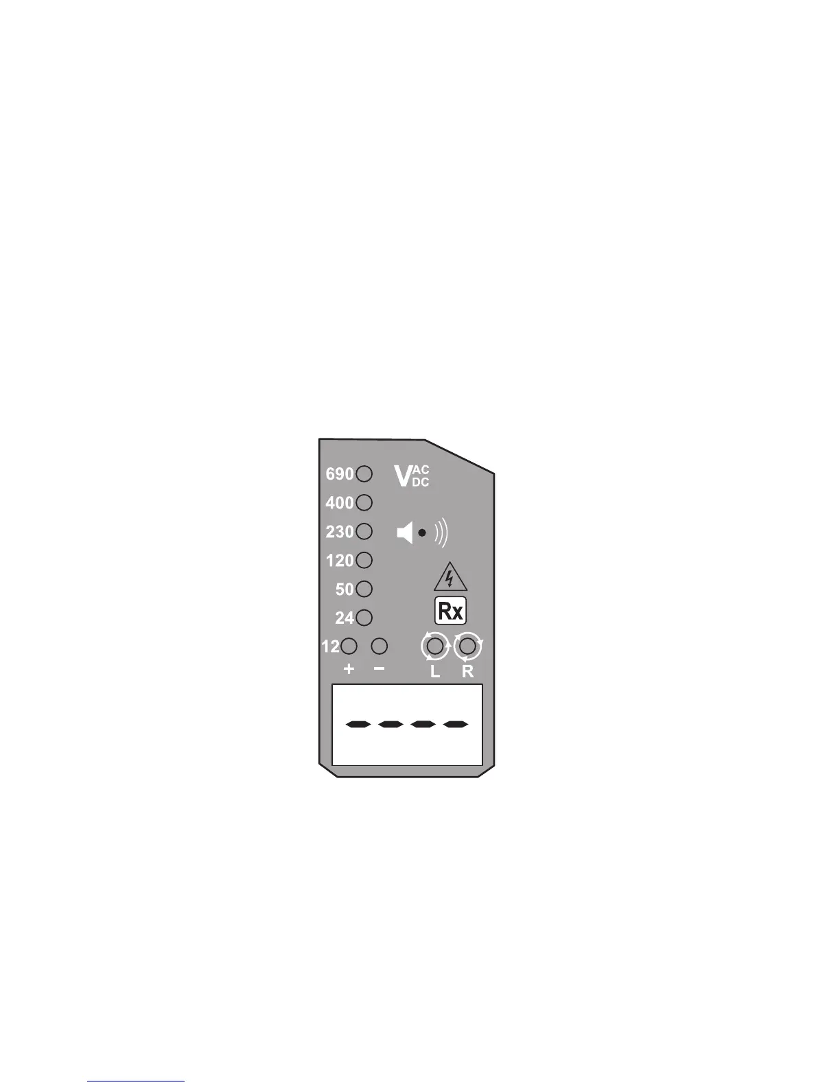
If only the voltage warning LED illuminates
(>50 VAC / >120 VDC) and the LCD display is
blank then check the batteries.
(This feature must not be used as a means
of continuing voltage indications.)
If the low battery indicator appears in the LCD
window then change the batteries.
Continuity test
Ensure the circuit under test is not energised.
Connect both test probes to the circuit. The
continuity LED illuminates and buzzer sounds
continuously to indicate continuity < 500 kW.
Note: No continuity measurement is available on
the LCD display.
Diode test
Connect the L1 - probe to the anode of the
diode and the L2 + probe to the cathode. The
continuity LED will illuminate and the buzzer
will sound. Reversing the connections, the
continuity LED will not illuminate and no sound
will be present.