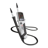
AC/DC Voltage test
Connect both probes to the circuit under
test. The voltage is indicated by LEDs and
the LCD display.
The buzzer sounds when a threshold voltage of
approximately 38 VAC or approximately 100 VDC
is exceeded.
Voltage polarity is indicated in following
manner.
AC: Both + and – 12 V LEDs are on.
+DC: +12 V LED is on.
-DC: -12 V LED is on.
When the L2 probe + is the positive (negative)
potential, the Polarity indication LED indicates
“+DC” (“-DC”).
During a voltage test, L or R LEDs may illuminate.
For voltages over 690 V the LCD will display ‘OL’.
Single-pole phase test
Hold the tester securely in your hand. Connect
the “L2 +” probe to the object under test.
Voltage warning LED lights up and buzzer sounds
when a voltage of approximately 100 V AC or
more exists in the object under test.
(Pol≥100 VAC).
Function of this test may not be fully achieved if the
insulation condition / grounding conditions of user or
of the equipment under test are not good enough.
Note: Verification of live-circuits should not be
dependent
on a Single-pole phase test only.

 Loading...