EasyManua.ls Logo

Megger PAT410 User Manual

Megger PAT410
92 pages
To Next Page IconTo Next Page
Page #1 background imageLoading...
Page #1 background image
WWW.MEGGER.COM
PAT400 Series
Portable Appliance Testers
User Manual

Table of Contents

Question and Answer IconNeed help?

Do you have a question about the Megger PAT410 and is the answer not in the manual?

Megger PAT410 Specifications

General IconGeneral
TypePortable Appliance Tester
Test Voltage250V, 500V
DisplayLCD
Power SupplyBattery
Power Supply Voltage6V
Protection RatingIP54
Operating Temperature Range-10°C to +50°C
Earth Bond Test Current25 A AC
Battery TypeAlkaline
Dimensions100 mm

Summary

Unpacking the Carton

UK Carton Contents

Lists items included in the UK packaging for PAT400 series.

European Carton Contents

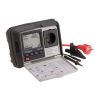
Lists items included in the European packaging for PAT400 series.

Safety Warnings

General Safety Precautions

Lists essential safety warnings and precautions for using the instrument.

Symbols Used on the Instrument

Electrical Hazard and Warning Symbols

Icons indicating electrical hazards and the need for caution.

Compliance, Disposal, and Battery Symbols

Symbols for EU compliance, electronic waste disposal, and battery type.

Test Lead Status and Mains Warning Symbols

Icons for test lead position and warnings against mains connection.

Instrument Layout

Overview of the PAT400

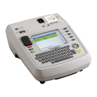
Introduces the PAT400 series testers and operating requirements.

Key Instrument Components

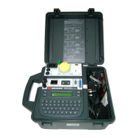
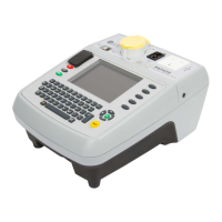
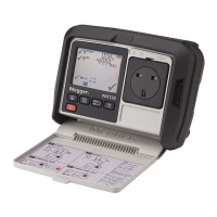
Identifies and describes physical components, controls, and display.

Button Functions

Primary Control Buttons

Describes the function of power, home, and escape buttons.

Hotkey Button Functions

Explains the purpose of hotkey buttons for quick access.

HOT KEY Descriptions

Hotkeys by Screen Context

Categorizes hotkeys based on their availability in Home, Setup, or other screens.

Display Information

Screen Display Areas

Describes the menu bar, main display, and additional menu option areas.

Screen Navigation

Navigation Controls and Actions

Explains using arrow keys, OK, HOME, and ESC for navigation.

Text Fields and Drop Down Boxes

Free Form Input Fields

Describes fields for manual text or number entry.

Drop Down Selection Fields

Describes fields with pre-defined lists of options.

Battery and Fuse Management

Battery and Fuse Specifications

Details the types of batteries and fuses used in the PAT400.

Replacement Procedures and Warnings

Provides steps for replacing battery and fuses, including warnings.

Getting Started

Initial Power-Up and Setup

Instructions for connecting, powering on, and initial setup.

Initialisation Warnings

HOME Screen Overview

HOME Screen Menu Functions

Details the options and sections available in the HOME screen menu.

Powering Off the PAT400

Normal Power-Off Procedure

Steps for a standard shutdown procedure of the instrument.

FAST Re-start Mode Explanation

Explains the hibernation mode for quick restarts after power loss.

Testing with a PAT400

Connecting Assets for Testing

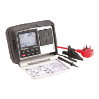
General instructions for connecting Class I/II assets, IEC cords, and 110V leads.

Connecting Extension Leads and RCDs

Testing an Asset

Test Group Selection Methods

Describes methods to start testing using hotkeys or the TEST button.

Asset Database Interaction

Asset Lookup and Adding New Assets

Procedure for searching existing assets and adding new ones.

Barcode Scanner Test Initiation

Test Progress

Test Screen and Results Display

Shows the test progress screen and explains result indicators.

Remote Probe and Clip

Remote Probe Usage and Application

Explains when and how to use the remote probe, with an example.

Test Lead Resistance Nulling Procedure

Extension Lead Adaptor Nulling Procedure

Short Circuit Asset Warning

Aborting a Test

Test Completion

Test Completion Options

Lists available actions after a test sequence is completed.

Test Fail Screen

Visual Failure Logging

Visual Test Failure Entry and Details

Procedure for logging visual failures, including notes and codes.

Repair Code Entry

Repair Code Examples

Provides a list of common repair codes and their descriptions.

Cable Compensation

Warnings

Power-On, Supply, and Earth Fault Warnings

Covers warnings for power-on tests, reversed supply, and earth faults.

Parallel Earth Path and Database Warnings

Addresses warnings for parallel earth paths and full database.

Using Memory

Memory Storage Overview

Explains client/location structure and asset ID rules for memory storage.

Saving Assets to Memory

Describes how to save asset data before or after testing.

Field Definitions for Asset Data

Saving Test Results

Saving Results and Printing Labels

Procedure for saving test results and printing barcode labels.

Adding Assets to Memory

Adding Assets Before Testing

Steps to add asset information before performing tests.

Copying Existing Assets

How to copy existing asset data to create new entries.

Editing and Deleting Assets

Editing Asset Data

Procedure to modify existing asset information.

Deleting Assets

Data Transfer

Backup to USB Memory Stick

Instructions for backing up instrument data to a USB drive.

Importing and Restoring Data from USB

Exporting Results to CSV

Accessing Test Results

Printing Barcode Labels

Test Groups

Overview and Creation of Test Groups

Explains the purpose and provides steps for creating test groups.

Allocating Test Groups to Hotkeys

Editing a Test Group

Deleting a Test Group

Repeated Tests

Quick Test - QT

Performing a Quick Test

Instructions on how to perform tests using the Quick Test function.

Setup Menu Options

Client Management Procedures

Covers adding, editing, and deleting client information.

Editing and Deleting Clients

Location Management Procedures

Adding Location Entries

Steps to add new location entries for a client.

Editing and Deleting Locations

Changing Locations

Company Details Entry

Quick Test Time Configuration

Date and Time Settings

Language Selection

Restoring Default Settings

About - Software Version and Contact Information

PAT400 Enhancements (Firmware V2.40)

User Account Management Features

Covers multiple operator accounts, login, and status.

Power Up and Login/Logout Options

Login with Multiple Accounts

Account Status Levels

Logging Out and Powering Down

Procedures for logging out and powering down the instrument.

Supervisor and User Status Explanations

Explains the difference between Supervisor and User account levels.

Expert Options Configuration

PIN Number Management

Changing Default Supervisor Account

Procedure to change the default administrator account name.

Adding PIN to an Account

Step-by-step guide to setting a PIN for an account.

Changing an Account PIN

Removing PIN from an Account

Adding Additional User Accounts

Deleting User Accounts

Recovery Login

Login Recovery Procedure

Steps for recovering login access by clearing users.

Reverse L-N Polarity

Enabling Reverse L-N Polarity Testing

How to activate reverse polarity testing for leakage tests.

Reverse L-N Polarity via Expert Options

Measure PE Option

Configuring Measure PE Option

How to enable/disable skipping PE bond testing.

PAT4 Compatibility

Feature and Storage Comparisons

Compares PAT400 features, storage, and Asset ID usage with PAT4.

Care and Maintenance

Carry Case

Appendix A - Test Types Explained

Continuity & Bond Testing

Explains continuity and bond testing methods and their differences.

Insulation Testing

Leakage Testing

Touch Current Test

Load Testing

RCD Testing

Power Lead/Extension Lead Testing

Flash Testing (PAT450 Only)

Parallel Earth Path Warnings

PAT400 Factory Default Test Groups

Appendix C - Specification

Electrical Supply Range

Specifies the acceptable input voltage and frequency ranges.

Bond Test Specifications

Details specifications for 10A and 25A bond tests.

Continuity Test Specifications

Insulation Test Specifications

Substitute Leakage Test Specifications

Leakage and Touch Current Specifications

Operational and Extension Lead Specifications

Flash and RCD Test Specifications

Appendix D - Ordering Information

Included Accessories

Lists standard accessories included with the instrument.

Optional Accessories

Lists optional accessories available for purchase.

Appendix E - Repair and Warranty

Instrument Handling and Protection

Precautions for handling sensitive internal components.

Warranty and Service Procedures

Details warranty and procedures for returning the instrument for service.

Related product manuals