Do you have a question about the Member's Mark GR2334401-MM-00 and is the answer not in the manual?
Read all instructions, use vendor hardware, check connections, follow warnings.
Use scratch-free surface, inventory parts, avoid power tools, do not fully tighten.
Use a soft cloth for cleaning; gloves recommended for assembly.
Conform to local codes and national fuel gas codes for installation.
Inspect hose for leaks, cuts, wear, or damage before using.
Must use 20 lb. capacity cylinder with Type 1 valve and OPD.
Steps for closing valve, placing cylinder, and attaching regulator.
Use manufacturer-supplied regulator/hose; use dust cap on valve outlet when not in use.
Steps for connecting regulator to tank valve, including leak testing.
Procedure for safely disconnecting the gas supply from the cylinder.
Interpreting flame color and behavior for proper burner operation.
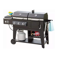
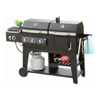
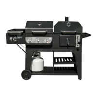
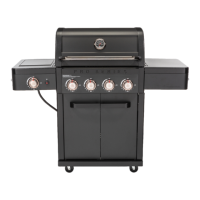
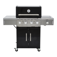
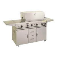
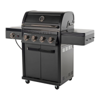
Overall size of the assembled gas grill.
Maximum weight the grill can support.
Details of bolts, screws, and other fasteners used for assembly.
List of tools needed for assembly, including provided and external tools.
Connect front and rear cart frames with connecting tubes and bolts.
Attach left and right cart panels to the cart assembly.
Secure the cart base assembly to the cart frame using M6x35 bolts.
Attach door stopping bracket to the cart base with M4x10 bolts.
Attach locking and directional casters to the cart assembly using M6x12 bolts.
Fully tighten all cart bolts and lock the casters for stability.
Attach door handles and bezels to the left and right doors using M6x10 bolts.
Secure the assembled doors to the cart assembly using M4x10 silver bolts.
Install the tank heat shield onto the cart assembly using M4x10 black bolts.
Carefully place and secure the grill body assembly onto the cart with M6x12 bolts.
Disassemble and attach thermometer, bezel, nut, and washer to the grill lid.
Connect the left side table panel to the left side table using M6x12 bolts.
Adjust and secure the left side table assembly to the grill body and control panel.
Attach the side burner control panel to the side burner frame assembly.
Adjust and secure the right side burner assembly to the grill body.
Install side burner valve into the burner port and secure to control panel.
Connect ignition wire to electrode and attach control knob to side burner valve.
Slide the grease collecting tray into its holding bracket at the bottom.
Slide the grease cup into the holding bracket at the bottom of the grease tray.
Position the flame tamers correctly onto the grill.
Place warming rack, cooking grates, and side burner grate on the grill.
Install LR6/AA battery into the igniter.
Confirm unit is fully assembled and review manual before use.
Product may expose to chemicals known to cause cancer or birth defects.
Appliance for outdoor use only; maintain minimum 60-inch clearance from combustibles.
Avoid moving grill when hot, lock wheels, wear gloves, keep away from combustibles.
Allow qualified dealers to fill cylinders to 80% capacity; use safety cap.
Remove packing material, prepare soap solution, ensure LP cylinder is full.
Apply soap solution to connections, check for bubbles indicating leaks.
Tighten fittings if leaks are found; contact customer service if leaks persist.
Inspect hose, do not use if gas odor is present, use correct regulator, keep face away.
Do not store spare cylinders nearby; do not fill beyond 80%.
Avoid POL valves, overfilled cylinders, or foreign objects in valve outlet.
Solutions for burners not lighting or having improper flames.
Addressing issues like low heat, high heat, or flame blowouts.
Step-by-step guide for lighting main and side burners using the electronic igniter.
Procedure for lighting burners using a match holder if electronic igniter fails.
General cautions for cleaning, keeping area clear, and checking ventilation.
Methods for cleaning and maintaining stainless steel components.
Instructions for emptying and cleaning the grease collection cup.
Guidelines for cleaning burner tubes to prevent flashback and ensure performance.
Tips for clearing clogged ports and contacting service for obstructions.
Steps for removing and reinstalling main burners for maintenance or replacement.
Procedure for removing and replacing the side burner.
Ensuring correct installation for optimal burner flame performance.
Input ratings for main and side burners in BTU/HR.
Details on product warranty period, coverage, exclusions, and limitations.
Instructions for contacting customer service for assistance and part replacement.
| Brand | Member's Mark |
|---|---|
| Model | GR2334401-MM-00 |
| Category | Grill |
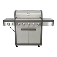
| Number of Burners | 4 |
| Material | Stainless Steel |
| Ignition Type | Electronic |
| Fuel Type | Propane |
| BTU Output | 48, 000 BTU |