ELECTRICAL ADJUSTMENTS
D-1
2. BASIC ADJUSTMENTS
Fig. 1-2
NO.
01
02
03
04
05
06
07
08
09
10
11
12
13
14
15
16
17
18
19
20
21
22
23
24
25
26
27
28
29
30
31
32
33
34
FUNCTION
CONT. AV(MIN)
COL. AV(CENT.)
COL. AV(MAX)
COL. AV(MIN)
TINT AV
SHARPNESS AV
SUB BIAS
BRI. DVD(CENT.)
BRI. DVD(MAX)
BRI. DVD(MIN)
CONT. DVD(CENT.)
CONT. DVD(MAX)
CONT. DVD(MIN)
COL. DVD(CENT.)
COL. DVD(MAX)
COL. DVD(MIN)
TINT DVD
SHARPNESS DVD
SUB BIAS
BRI. GAME(CENT.)
BRI. GAME(MAX)
BRI. GAME(MIN)
CONT. GAME(CENT.)
CONT. GAME(MAX)
CONT. GAME(MIN)
SUB BIAS
TUNING V MUTE
POWER ON V MUTE
INPUT LEVEL
SEPARATION L
SEPARATION H
X-RAY TEST
H.STOP
H.FREQ
NO.
35
36
37
38
39
40
41
42
43
44
45
46
47
48
49
50
51
52
53
54
55
56
57
58
59
60
61
62
63
64
65
66
67
68
FUNCTION
OSD H
OSD CONTRAST
CUT OFF
H POSITION
H.BLK L
H.BLK R
V SIZE
V POSITION
V LINEARITY
V S CORRECTION
V.COMP
R CUT OFF
G CUT OFF
B CUT OFF
R DRIVE
G DRIVE
B DRIVE
BRIGHTNESS(CENT.)
BRIGHTNESS(MAX)
BRIGHTNESS(MIN)
CONTRAST(CENT.)
CONTRAST(MAX)
CONTRAST(MIN)
COLOR(CENT.)
COLOR(MAX)
COLOR(MIN)
TINT
SHARPNESS
SUB BIAS
BRI. AV(CENT.)
BRI. AV(MAX)
BRI. AV(MIN)
CONT. AV(CENT.)
CONT. AV(MAX)
1.
Read and perform these adjustments when repairing the
circuits or replacing electrical parts or PCB assemblies.
CAUTION
•
•
•
•
Use an isolation transformer when performing any
service on this chassis.
Before removing the anode cap, discharge electricity
because it contains high voltage.
When removing a PCB or related component, after
unfastening or changing a wire, be sure to put the wire
back in its original position.
When you exchange IC and Transistor for a heat sink,
apply the silicon grease (YG6260M) on the contact
section of the heat sink. Before applying new silicon
grease, remove all the old silicon grease. (Old grease
may cause damages to the IC and Transistor).
BEFORE MAKING ELECTRICAL
ADJUSTMENTS
Prepare the following measurement tools for electrical
adjustments.
1. Oscilloscope
2. Digital Voltmeter
3. AC Voltmeter
4. Pattern Generator
5. Multi-Sound Signal Generator
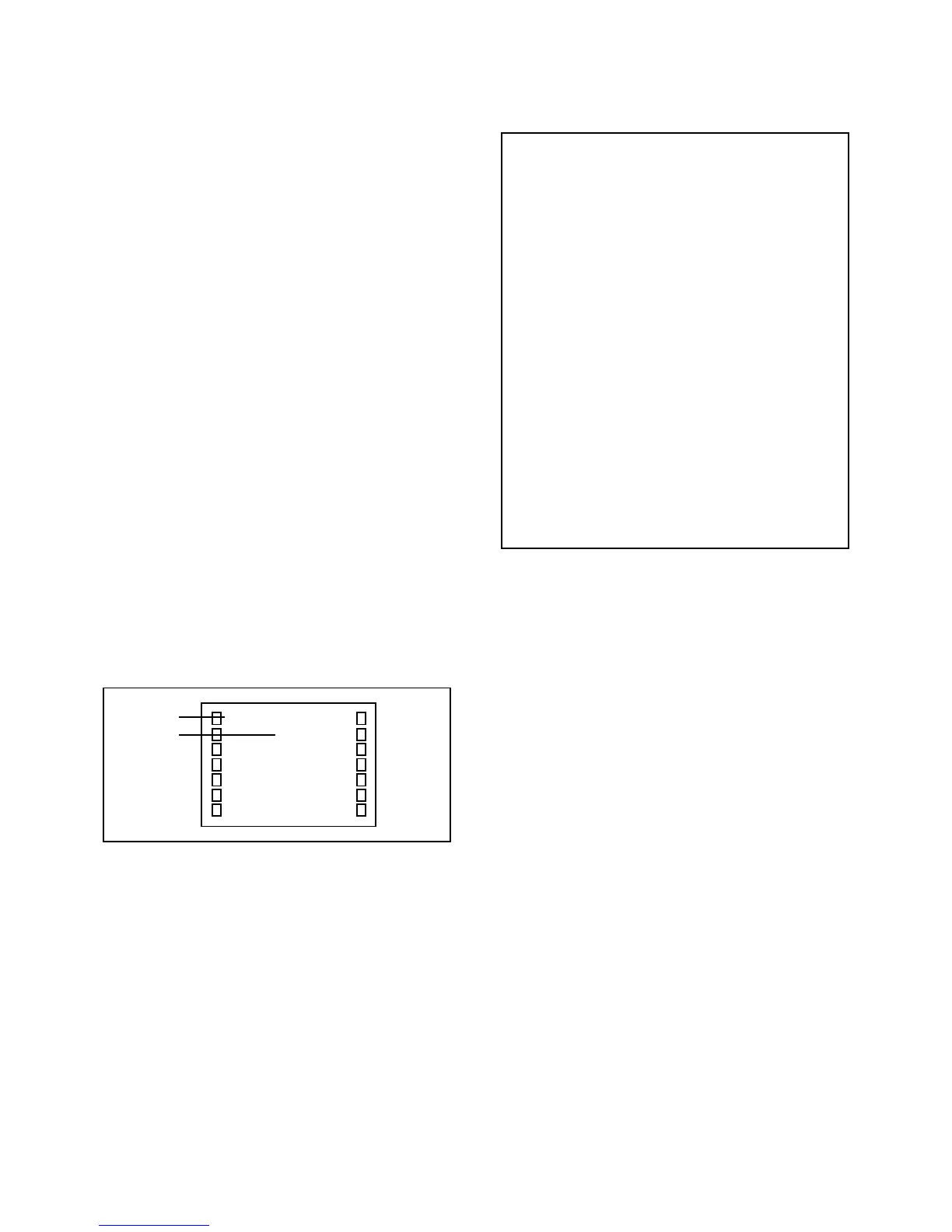
On-Screen Display Adjustment
In the condition of NO indication on the screen.
Press the VOL. DOWN button on the set and the
Channel button (9) on the remote control for more than
1 second to appear the adjustment mode on the screen
as shown in Fig. 1-1.
1.
Fig. 1-1
Use the Channel UP/DOWN button or Channel button
(1-0) on the remote control to select the options shown
in Fig. 1-2.
Press the MENU button on the remote control to end
the adjustments.
2.
3.
Function
Step No.
2-1: CONSTANT VOLTAGE
1.
2.
3.
4.
5.
6.
Input DC12V to DC Jack and turn the Power ON.
Connect the digital voltmeter to the TP3801.
Set condition is AV MODE without signal.
Adjust the VR3801 until the digital voltmeter is 101 ± 0.5V.
Input AC120V to AC cord, and then remove the DC Jack
cord.
Adjust the VR3802 until the digital voltmeter is 102 ± 0.5V.
TV
01 OSD
15
2-4: CUT OFF
1.
2.
3.
4.
5.
6.
Adjust the unit to the following settings.
R CUT=7F, G CUT=7F, B CUT=7F, R DRV=3F,
G DRV=05, B DRV=3F
Place the set with Aging Test for more than 15 minutes.
Set condition is AV MODE without signal.
Using the remote control, set the brightness and contrast
to normal position.
Activate the adjustment mode display of Fig. 1-1 and
press the channel button (03) on the remote control to
select "CUT OFF".
Adjust the Screen Volume until a dim raster is obtained.
2-2: FOCUS
1.
2.
3.
Receive the monoscope pattern.
Turn the Focus Volume fully counterclockwise once.
Adjust the Focus Volume until picture is distinct.
1.
2.
3.
4.
Receive the VHF HIGH (70dB).
Connect the AC voltmeter to pin 6 of CP101.
Activate the adjustment mode display of Fig. 1-1 and
press the channel button (63) on the remote control to
select "LVL".
Press the RIGHT/LEFT button on the remote control
until the AC voltmeter is 80 ± 2mV.
2-3: LEVEL
 Loading...