Smoke and Heat Exhaust Control Unit mcr 9705 – User Instruction Manual
Strona 5 z 24
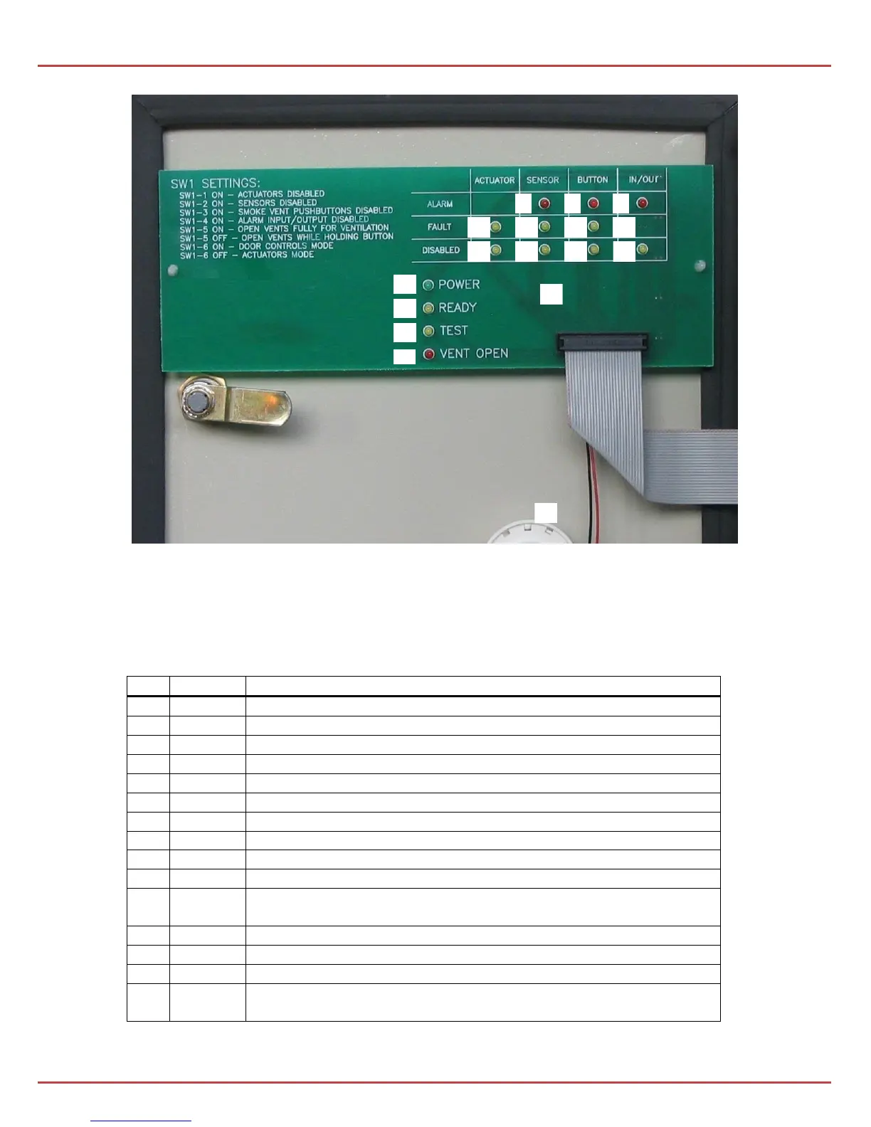
Pic. 2 Inside view of the control unit’s door.
On the inside of the control unit’s door there’s an audio alarm device (22) and the
optical indicator board (23). Optical indicators are used for the system diagnostics:
alarm; source: sensor line
alarm; source: pushbutton line
alarm; source: external input terminal
defect to the actuator line (line gap)
defect to the sensor line (line gap)
defect to the pushbutton line (line gap or short-circuit)
disconnection of the sensor line (SW1-2)
disconnection of the pushbutton line (SW1-3)
disconnection of the in/out connectors providing information
about alarm and defect (SW1-4)
power supply (same as on the front panel)
ready (same as on the front panel)
check – testing the correct operation of signals
indication of open vent or dropped curtain (same as on the front
panel)