Smoke and Heat Exhaust Control Unit mcr 9705 – User Instruction Manual
Strona 7 z 24
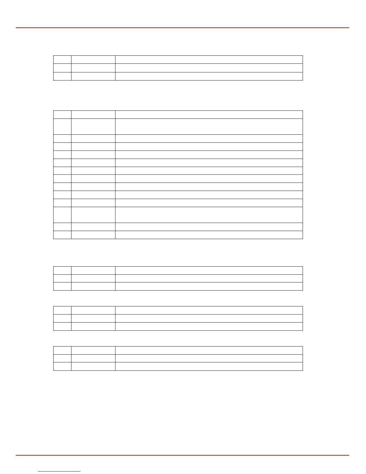
Above the RESET pushbutton there are jumpers regulating the vent’s opening time in
ventilation and entrance mode (combinations of settings can be found in Chap. 3.2):
depending on the combination created with the H5 jumper
depending on the combination created with the H6 jumper
Along the top edge of the module's PCB there are terminal strips which are used to
connect the system’s elements:
Input for ventilation (U-up, D-down, ┴ - joint, closing
contacts)
input for wind/rain controls (closing contact)
output for actuators (-,+)
control input from ROP-1 (R,U)
power supply of the alarm signal loop (+, -)
external alarm input, 24V= relay
alarm indication output - relay contact
defect indication output - relay contact
programmable / service output (ex. opening the vent/ door
closing) - relay contact
RPO-1 indication output (1, 2, 3)
power supply for alarm signaling loop (-, +)
Note: For control units designed for the purpose of a smoke curtain, above the elements [30,44]
there is additional 4 poles terminal strip for mcr PROSMOKE CE/CE1 curtains’ actuators.
There are two additional entries in the upper right corner:
programmable / service input
Moreover, in the lower right corner there are:
positive pole of the battery
negative pole of the battery
batteries protection (6.3 A or 8 A
*
quick)
actuator’s line protection (6.3 A or 8 A
*
quick)
230 V 50 Hz power supply is connected to the terminal strip (42) in the top left
corner of the assembly board (inside the control unit).
Overload circuit breaker FS2 (45) – C 4 A or 6 A
*
on the assembly board
provides protection for the 230 V mains circuit and the possibility for disconnecting
power supply.