EasyManuals Logo

Mercury 150 EFI User Manual

Mercury 150 EFI
631 pages
To Next Page IconTo Next Page
To Previous Page IconTo Previous Page
Page #169 background imageLoading...
Page #169 background image
WIRING DIAGRAMS
Page 2D-16 90-883728 JULY 2001
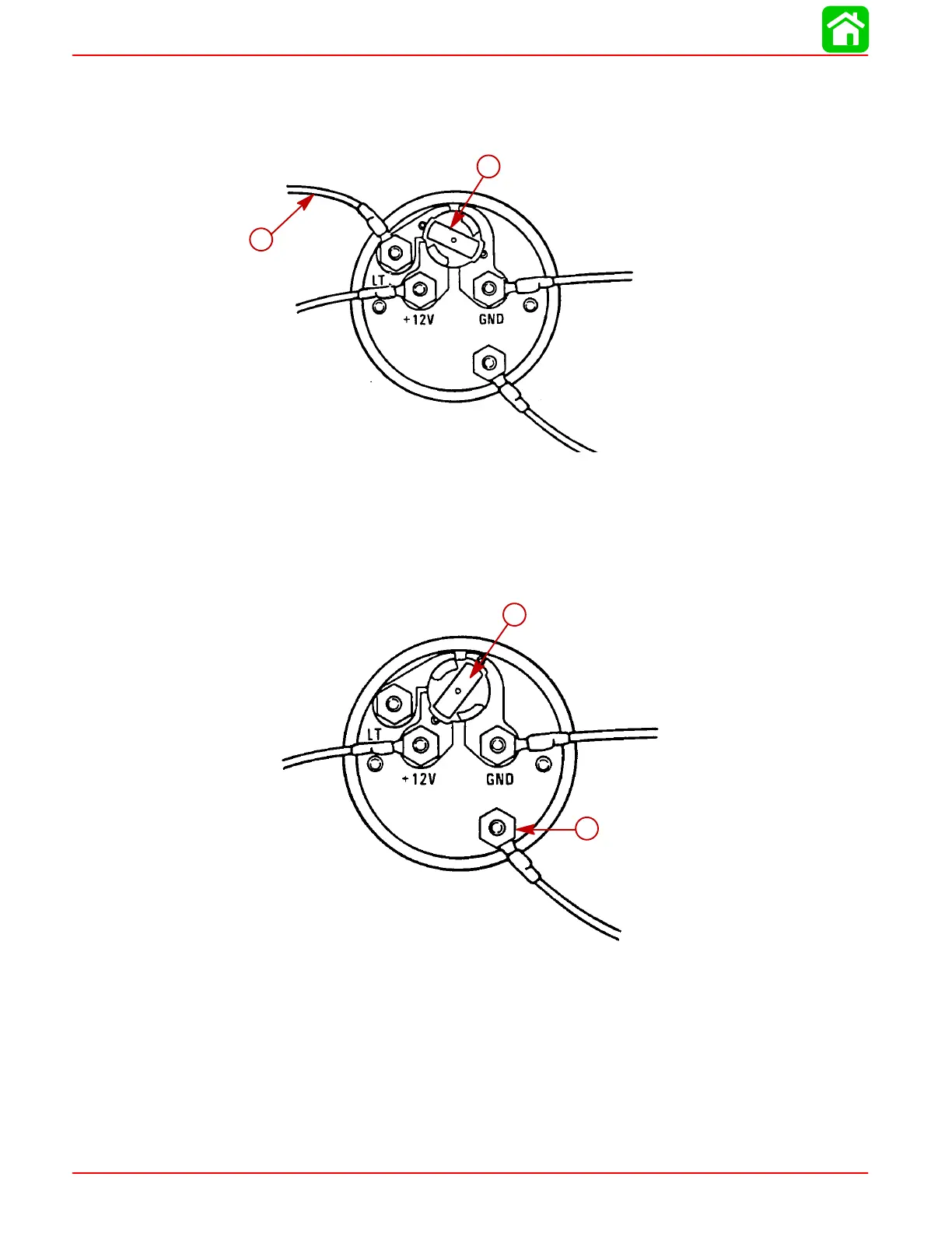
Engine Synchronizer Wiring Diagram
LIGHT BULB POSITION A
Use this position when using a separate light switch for instrument lighting.
SEND
51105
a
b
a-+12 Volt Light Switch Wire
b-Position Light Bulb to the Unswitched Position
LIGHT BULB POSITION B
Use this position when instrument lighting is wired directly to the ignition key switch.
(Instrument lights are on when ignition key switch is turned on.)
51106
a
b
a-Position Light Bulb to the Switched Position
b-Sender

Table of Contents

Questions and Answers:

Question and Answer IconNeed help?

Do you have a question about the Mercury 150 EFI and is the answer not in the manual?

Mercury 150 EFI Specifications

General IconGeneral
Engine Type4-stroke
Displacement3.0L
Horsepower150 HP
Fuel Induction SystemElectronic Fuel Injection (EFI)
Alternator60 amp / 756 watt
Gear Ratio1.92:1
Cylinders4
StartingElectric
Warranty3 years
Shaft Length20", 25"
Weight455 lbs
Full Throttle RPM Range5000-5800 RPM

Related product manuals