ATTACHMENTS / CONTROL LINKAGE
Page 7-14 90-883728 JULY 2001
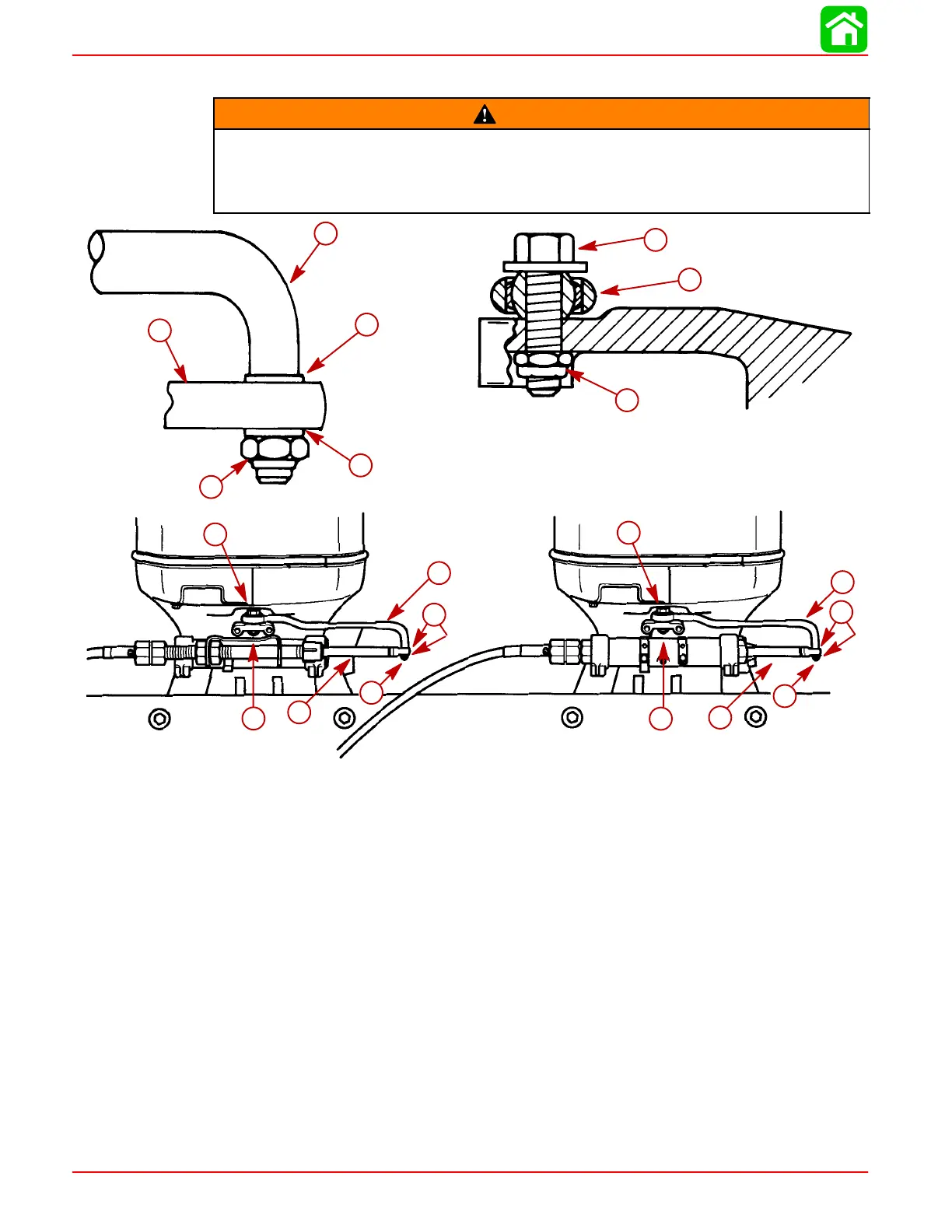
STEERING LINK ROD INSTALLATION
WARNING
Steering link rods MUST BE secured between outboard steering arm and steering
cable end, using special washer head bolt (10-849838) and two nylon insert lock-
nuts (11-826709113), as shown. Both special washer head bolt and nylon insert
locknuts MUST BE tightened as specified.
50061
28166
e
a
b
f
d
c
e
a
b
f
d
c
a
b
f
e
a
c
e
d
a-Flat Washer (2 Each Link Rod)
b-Nylon Insert Locknut - Torque Until it Seats [DO NOT Exceed 120 lb. in. (13.5
Nm) of Torque], Then Back Off 1/4 Turn
c-Special Washer Head Bolt (10-849838) - Torque to 20 lb. ft. (27 Nm)
d-Nylon Insert Locknut - Torque to 20 lb. ft. (27 Nm)
e-Steering Link Rod
f-Steering Cable End
Lubricate holes in ends of steering cables, with Quicksilver 2-4-C with Teflon Marine Lu-
bricant. Assemble steering link rods to steering cable ends of each outboard, using flat
washers and nylon insert locknuts. Tighten locknuts until they seat [DO NOT exceed 120
Ib. in. (13.5 Nm) of torque], then back nut off 1/4 turn.
Lubricate ball joints in steering link rods with SAE 30W Motor Oil. Secure link rods to out-
board steering arms, using special washer head bolts (10-849838) provided and nylon
insert locknuts as shown. Torque special bolts to 20 Ib. ft. (27 Nm) then torque locknuts
to 20 Ib. ft. (27 Nm).
 Loading...


