MIE MODELS - HURTH TRANSMISSION SERVICE MANUAL NUMBER 23
Page 2D-8 90-861326--1 MARCH 1999
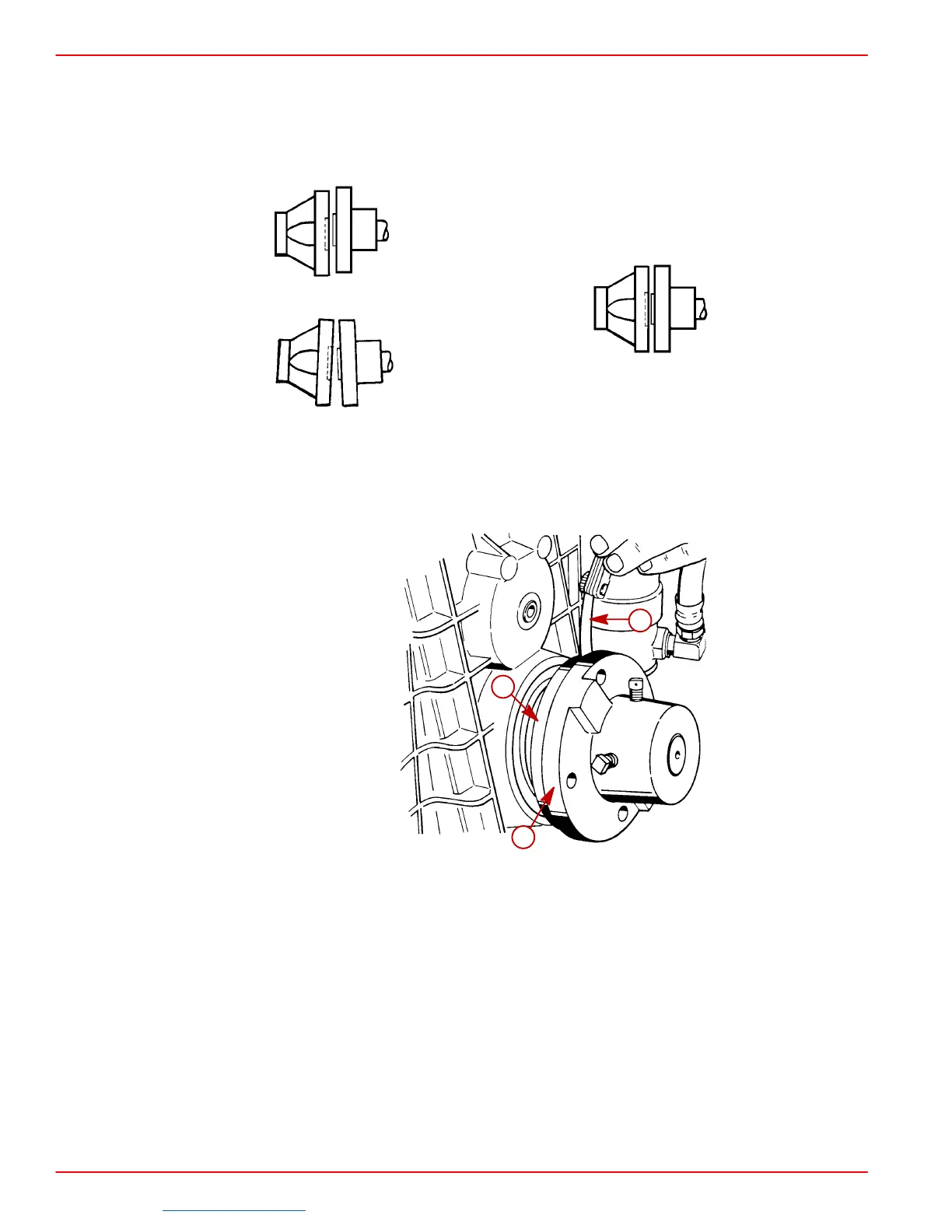
3. Ensure coupling centerlines align by butting propeller shaft coupler against transmis-
sion output flange. Shoulder on propeller shaft coupler should engage recess on trans-
mission output flange face with no resistance.
NOTE: Some propeller shaft couplers may not have a shoulder on mating face. On these
installations, use a straight edge to check centerline alignment.
72597
Wrong Right
4. Check for angular misalignment, by hand holding coupling faces tightly together; check
for a gap between faces with a .003 in. (0.07 mm) feeler gauge at 90° intervals.
50609
a
b
c
V-Drive Shown - Down Angle Similar
a-Feeler Gauge (Check At 90 Degree Intervals)
b-Transmission Output Flange
c-Propeller Shaft Coupler
Downloaded from https://needmanual.com/!
 Loading...

