DIRECT FUEL INJECTION
Page 3B-48
90-888438 JUNE 2002
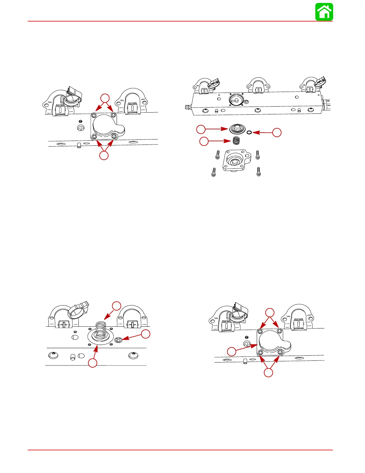
TRACKER VALVE REMOVAL
1. Remove 4 screws securing tracker valve and remove tracker assembly.
2. Inspect tracker diaphragm for cuts and tears.
3. Inspect tracker cover o-ring for cuts and abraisions. Replace components as re-
quired.
a
a
57802
58009
b
c
d
a-Screws
b-Diaphragm
c-Spring
d-O-Ring
TRACKER VALVE INSTALLATION
NOTE: Apply a light coat of 2-4-C with Teflon to tracker diaphragm and cover o-ring to
aid in their retention on fuel rail while reinstalling tracker valve to fuel rail.
NOTE: Apply anti-seize grease (obtain locally) or 2-4-C with Teflon to tracker valve at-
taching screw threads.
1. Position diaphragm, spring and o-ring onto fuel rail.
2. Place cover over diaphragm/spring/o-ring assembly and secure with 4 screws.
Torque screws to 70 lb. in. (8.0 Nm).
b
e
e
d
57802
c
b
b
a
a
57919
a-Diaphragm
b-Spring
c-O-Ring
d-Cover
e-Screws [Torque to 70 lb. in. (8.0 Nm)]

 Loading...


