DIRECT FUEL INJECTION
Page 3B-59
90-888438 JUNE 2002
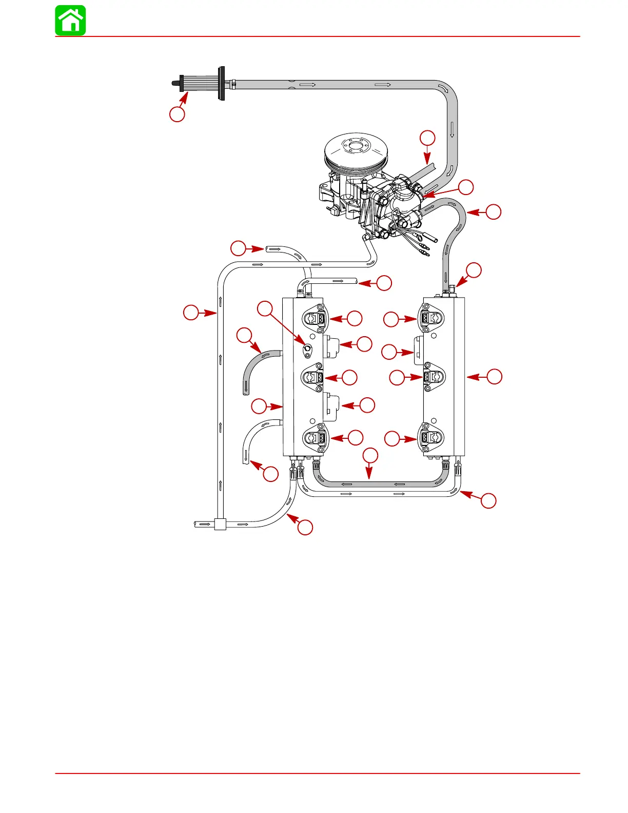
Air Compressor Flow Diagram
00027
a
b
c
w
d
h
j
e
f
g
i
c
k
l
m
n
o
p
j
v
q
s
r
t
u
a-Air Filter
b-Compressor Air Inlet
c-Air [80 ± 2 psi (551.6 ± 13.8 kPa)]
d-Fuel System Pressure Test Valve
e-#1 Fuel Injector
f-Tracker Valve
g-#3 Fuel Injector
h-Starboard Fuel Rail
i-#5 Fuel Injector
j-High Pressure Fuel [90 ± 2 psi (620.5 ± 13.8
kPa)]
k-#6 Fuel Injector
l-Fuel Regulator [90 ± 2 psi (620.5 ± 13.8
kPa)]
m-#4 Fuel Injector
n-Air Regulator [80 ± 2 psi (551.6 ± 13.8 kPa)]
o-#2 Fuel Injector
p-Rail Water to Expansion Chamber
q-Port Fuel Rail
r-Air Pressure Test Valve
s-Excess Air Return to Adapter Plate
t-Excess Fuel Return to VST
u-Water Inlet to Fuel Rail
v-Water Inlet to Compressor
w-Compressor Water to Expansion Chamber

 Loading...


