20
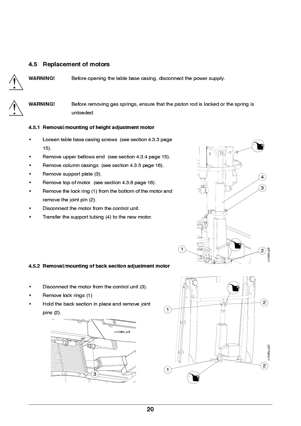
4.5 Replacement of motors
WARNING!
Before opening the table base casing, disconnect the power supply.
WARNING!
Before removing gas springs, ensure that the piston rod is locked or the spring is
unloaded.
4.5.1 Removal/mounting of height adjustment motor
• Loosen t a bl e bas e c as in g sc rew s ( see sec t i o n 4 . 3 . 3 page
15).
• Remove upper bellows end (see section 4.3.4 page 15).
• Re m ove colu m n cas in g s (see se ction 4.3.5 p ag e 16).
• Remove support plate (3).
• Remove top of motor (see section 4.3.6 page 16).
• Remove the lock ring (1) from the bott om of the motor and
remove the joint pin (2).
• D isconn ect the motor from the control unit.
• Transfer the support tubing (4) to the new motor.
4.5.2 Removal/mounting of back section adjustment motor
• D isconn ect the motor from the control unit (3).
• Remove lock rings (1)
• Hold the ba ck se ction in pl ace an d rem ove joi nt
pins (2).
!
!
3
4
2
1
o
1
0
4
6
i
.
p
d
f
2
o
1
0
4
6
p
.
p
d
f
1
1
2
3
o1046x.pdf