58 Meru Access Point Installation Guide © 2010 Meru Networks, Inc.
Installing the Access Points
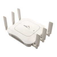
Figure 16: AP200 Antenna Connection
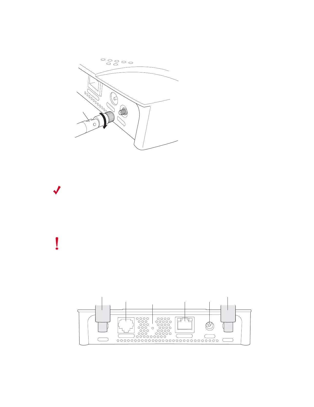
3. Connect one end of the PoE 100BaseT Ethernet cable to the 100/1000 Ethernet
connector, shown in Figure 17.
Turn clockwise
to tighten
ntenna
ETHERNET
3.3 VDC
ANT 2
Note:
For the AP201 and AP208 access points, a shielded Cat 5e (or greater)
Ethernet cable must be used in order to comply with international
electromagnetic emissions limits.
If it is not practical to use shielded cables, contact Support for a line filter,
available at no charge, that may also be used to ensure compliance.
Caution!
Be sure to connect the Ethernet cable to the Ethernet port; the cable can
mistakenly be plugged into the Console port (see Figure 17).
CONSOLE
ANT 1
ANT 2
3.3 VDC
ETHERNET
0108
100/1000
Ethernet
(Reserved)
Console
port
Antenna 1 Antenna 2
Power
inlet
Reset
(Push to restore
default settings)
unsupported)
 Loading...