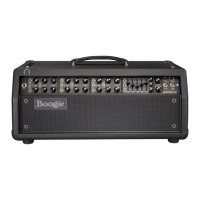
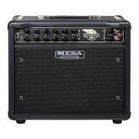
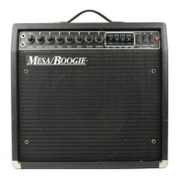
Do you have a question about the Mesa/Boogie SINGLE RECTIFIER RECT-O-VERB 50 2 Series and is the answer not in the manual?
Lists controls, types, and Mesa Part# for Channel 1.
Lists controls, types, and Mesa Part# for Channel 2.
Lists miscellaneous rear panel components including input/output and pilot light.
Details FX Loop controls, mix level, and external switch connections like Send/Return.
Lists components for fuse holder and AC receptacle on the rear panel.
Lists controls, types, and Mesa Part# for Channel 1 of the Solo 50.
Lists controls, types, and Mesa Part# for Channel 2 of the Solo 50.
Lists miscellaneous rear panel components for the Solo 50, including input/output.
Details FX Loop controls, mix level, and external switch connections for the Solo 50.
Lists components for fuse holder and AC receptacle on the Solo 50 rear panel.
Details the low voltage power supply circuits specific to the Rectoverb model.
Details the low voltage power supply circuit for the Solo 50 model.
Schematic diagram for the Channel 2 Lead preamp section.
Schematic diagram for the Channel 1 Rhythm preamp section.
Schematic diagram for the effects loop circuitry.
Schematic diagram for the reverb effect circuit.
Details the connection for the Slave output in the power amp section.
Details the switching matrix logic for the Solo circuit.
Details the switching matrix logic for the Mute circuit.
Explains grounding and wiring changes for a specific power transformer modification.
| Output Power | 50 Watts |
|---|---|
| Channels | 2 |
| Preamp Tubes | 5 x 12AX7 |
| Power Tubes | 2 x 6L6 |
| Effects Loop | Yes |
| Speaker Configuration | 1x12" |
| Speaker Outputs | 4 Ohm, 8 Ohm |
