16
Fig. 12 Fig. 13
LIGHT BLUE
LIGHT BLUE/GREEN
LIGHT BLUE/GREEN
LIGHT BLUE
CONTROL
FEEDBACK
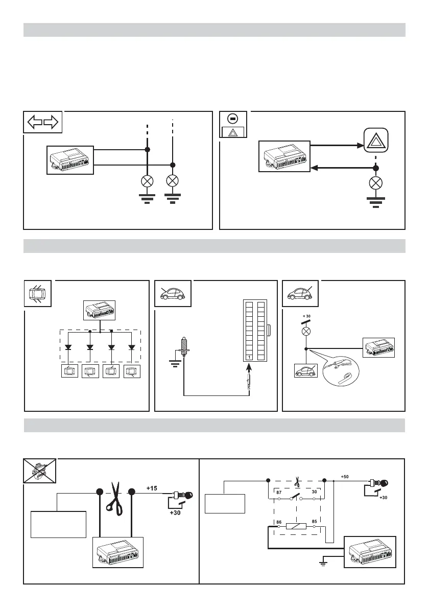
To control the blinkers during an alarm phase it is essential to connect the BLUE and BLUE/GREEN wires.
The product allows the blinkers to work either with the positive signals connected directly to the lamps (Fig. 12)
or controlling the negative signal directed to the car’s Blinker button (Fig. 13). Like the OEM alarms also the Meta
EasyCan EVO Digital unit has a feature of extending ashing of indicators for 25 sec. following the acoustic; to
exclude this feature you have to deactivate the selection nr°31 with the PRG007 programmer. If the car doesn’t has
the original ashes of the indicators during locking and unlocking the doors it’s necessary set ON both selections
nr°5 and nr°30 using programmer PRG007.
BLINKER
Use the existing push button only if they close to earth.
PROTECTION OF THE PERIPHERALS
An attempt to start the car with the control unit activated will activate the internal relay and open the ignition
block circuit.
IGNITION BLOCK
Fig. 14
+
Fig. 15 Fig. 16
DOORS ENGINE BONNET BOOT
Fig. 17a
Fig. 17b
M134 DIODE
MODULE OR
1N4002 (X4)
ORIGINAL
DOOR
SWITCHES
GREEN
MOUNT
BOOT
PROTECTION
SWITCH
PURPLE
COURT LIGHT
IN BOOT
ORIGINAL
BOOT
SWITCHES
PETROL PUMP
ELECTRONIC
INJECTION
STARTER
MOTOR
MOUNT AN
ADDITIONAL
30A RELAY
PURPLE
PURPLE
DARK BLUE
DARK BLUE
WHITE